
3
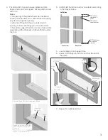
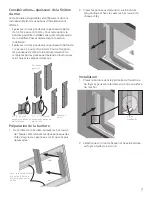
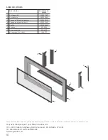
3. Position plinth in space between glass and trim,
locate ends onto end support. Ensure plinth is level
with trim.
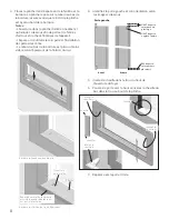
Notes :
- The opening in the plinth should be oriented as
shown below to allow air to enter while obstructing
any view through the opening.
- Each end of the plinth has a rounded notch
opening to insert the hinge pin of the side doors.
- The bottom edge of the trim is more or less visible
depending of the thickness of the wall finish under
the trim.
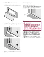
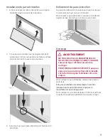
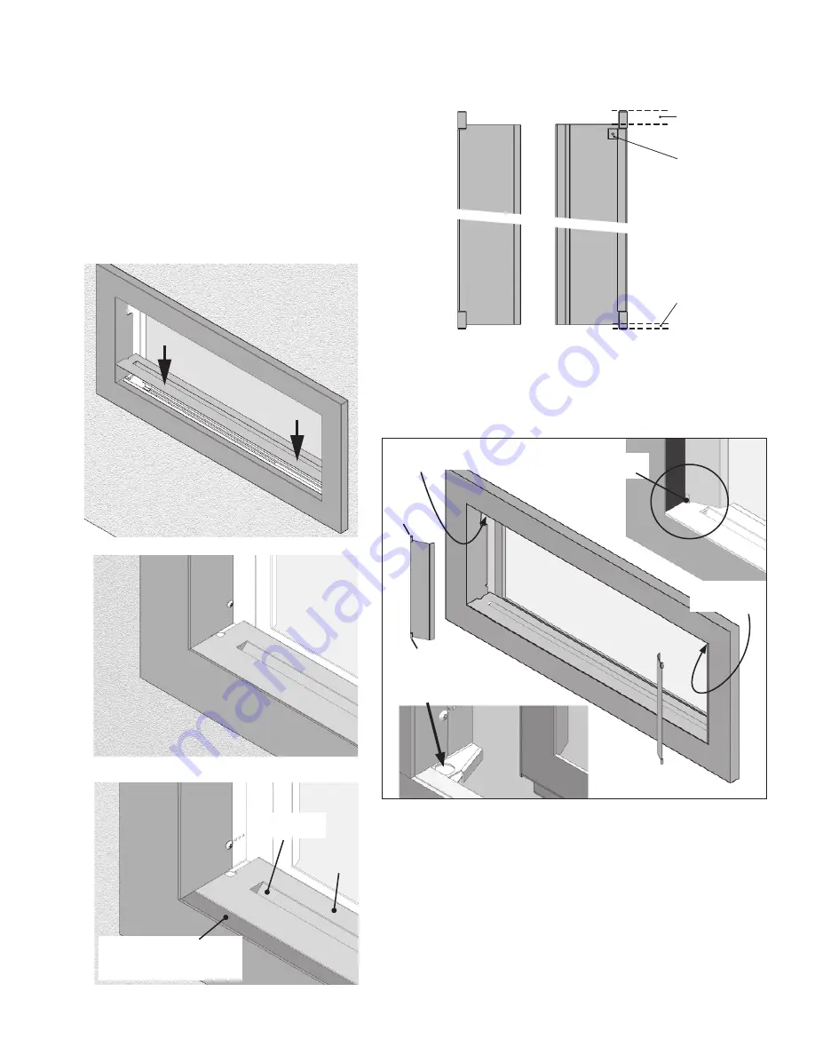
TOP of door:
this space is
wider
TOP of door:
tab at the rear
Left door
BOTTOM of door:
this space is
narrower
Rear view
Front view
4. Identify left hand door and its orientation according
to the images below.
5. Locate hinge pin into upper hole.
6. Lower door hinge pin into the notch at the end of
the plinth.
7. Repeat for right hand door.
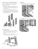
Trim directly on the finished cement board
Flange below plinth is visible
when the trim is on thicker
wall finish
Trim on 1” thick wall finish
Plinth
Opening in
the plinth
Insert tab
here
hinge pin
hinge
pin
hinge
pin
Insert hinge
pin here
Insert hinge
pin here


