background image

66

  Install Remote Control Handset  Wall 
Holder

The remote control kit for this fi replace comes complete 
with a wall-mounted holder. This holder is not required 
in all installations but is provided as an optional feature 
for those customers who wish to mount the remote 
handset to the wall.
To install the holder to the wall, fi nd a convenient 
location and use the hardware provided with the kit. 
See the diagram below for required hardware and 
confi gurations. Note that the holder can be installed at 
the base of a light switch plate.

IMPORTANT

. The location of the remote control 

handset is important to assure proper temperature 
regulation. To obtain a constant temperature, we 
recommend that the handset should be between 3 
and 15 feet away from the appliance 

but not directly 

above it

. We also advise that the handset should 

be located away from any other heat source and not 
in direct sunlight as this may aff ect the temperature 
sensor located in the remote handset.

INSTALLATION

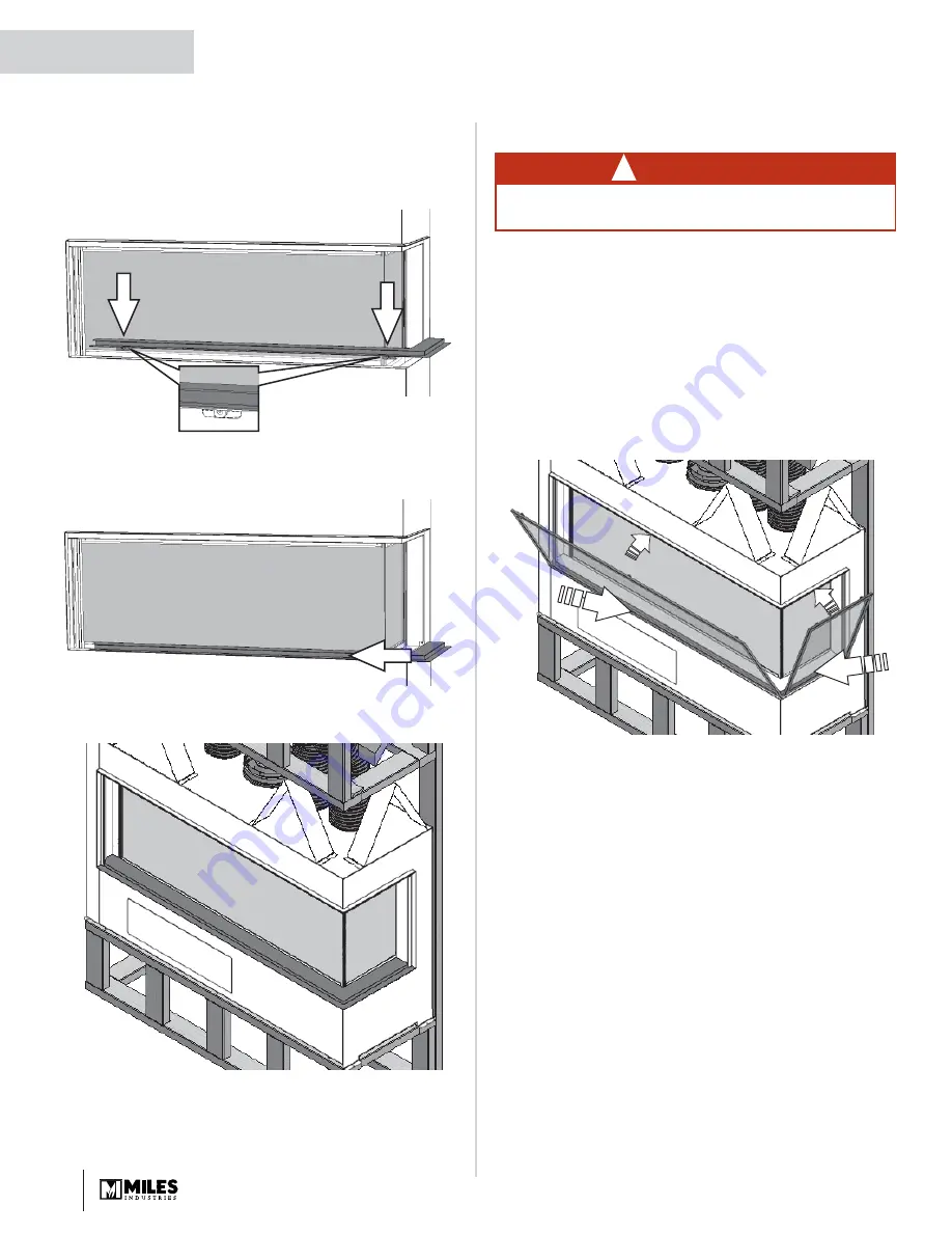
Reinstall Base Plate

1.  Place the base plate on the fi replace’s front fl ange 

with the 

magnets behind the fi replace’s front 

panel.

2.  Ensuring the plate is lined up with the fl ange, slide 

the plate sideways so both its ends butt with the 
vertical panels of the black frame.

3.  Pull the plate forward so it is fl ush with the 

fi replace’s front fl ange.

 Install  Barrier Screen

Install the  barrier screen onto the appliance. 
1.  Place the side screen on the base plate of the 

appliance opening, magnets inboard against plate 
fl ange. Push top against top plate fl ange.

2.  Place the front screen on the base plate of the 

appliance opening, magnets inboard against plate 
fl ange. Push top against top plate fl ange.
Note: The front screen frame overlaps the side 
screen frame.

3.  Ensure that the screens are secure.

WARNING

FOR SAFETY PURPOSE, ensure the barrier 
screen is installed on the fireplace.

!

QUALIFIED 
INSTALLER

Summary of Contents for LX2 Series

Page 1: ...e is suitable for installation in a bedroom or bed sitting room INSTALLER Leave this manual with the appliance CONSUMER Retain this manual for future reference Please read this manual BEFORE installin...

Page 2: ...Your Fireplace Cannot Be Turned ON Inadvertently 8 Using the Remote Control 9 Using the Wall Switch 15 Kits Accessories 15 Lighting Instructions 16 Maintaining Your Fireplace 17 Servicing Your Firepl...

Page 3: ...s Clothing or ammable material should not be placed on or near the appliance This unit must be used with a vent system as de scribed in this installation manual No other vent sys tem or components may...

Page 4: ...sk individuals in the house Install an approved after market safety gate to keep toddlers young children and other at risk individuals a safe distance from the replace Keep the remote control handset...

Page 5: ...ny parts of your replace even after it is turned o as it is still hot Use the barrier screen provided with the trim or a gate to reduce the risk of severe burns Keep the remote control handset out of...

Page 6: ...________ Phone Number _______________________________ Should you encounter an operational problem call your dealer immediately Do not try to repair the unit as you may cause an injury or damage the re...

Page 7: ...new replace for the rst time some vapors may be released due to the burning of curing compounds used in the manufacture of the appliance They may cause a slight odor and could cause the ames to be th...

Page 8: ...t turn o the replace wait 6 hours and the replace will automatically go to pilot You can then access the controls inside your replace Alternately turn o gas supply In all cases call your dealer for se...

Page 9: ...LFH PD QRW FDXVH KDUPIXO LQWHUIHUHQFH DQG WKLV GHYLFH PXVW DFFHSW DQ LQWHUIHUHQFH UHFHLYHG LQFOXGLQJ LQWHUIHUHQFH WKDW PD FDXVH XQGHVLUHG RSHUDWLRQ 127 HIRUH XVLQJ WKH UHPRWH FRQWURO V VWHP IRU WKH UV...

Page 10: ...VLXV KRXU FORFN DQG YLFH YHUVD 7KH WLPH GLVSOD ZLOO DVK DIWHU HLWKHU QVWDOOLQJ WKH EDWWHU RU 6LPXOWDQHRXVO SUHVVLQJ WKH ODUJH DPH DQG VPDOO DPH EXWWRQV 3UHVV ODUJH DPH EXWWRQ WR VHW WKH KRXU 3UHVV VPD...

Page 11: ...KW EXOE PRGH LJKW EXOE LFRQ DVKHV 3UHVV DQG KROG ODUJH DPH EXWWRQ WR WXUQ 21 WKH OLJKW RU LQFUHDVH EULJKWQHVV 3UHVV DQG KROG VPDOO DPH EXWWRQ WR GHFUHDVH EULJKWQHVV Q WKH LJKW LPPHU PRGH WKH 2 EXWWRQ...

Page 12: ...DLW WR FRPSOHWH SURJUDPPLQJ 6 77 1 7 7 0 7 03 5 785 6 77 1 7 1 77 0 6 7 7 03 5 785 HIDXOW 6HWWLQJV VXQ HIDXOW 6HWWLQJV PRRQ 2 3UHVV ODUJH DPH EXWWRQ WR LQFUHDVH 1LJKWWLPH 6HWEDFN 7HPSHUDWXUH 3UHVV VPD...

Page 13: ...DUJH DPH EXWWRQ WR VHW WKH KRXU 3UHVV ODUJH DPH EXWWRQ WR VHW WKH KRXU 3UHVV VPDOO DPH EXWWRQ WR VHW WKH PLQXWHV 3UHVV VPDOO DPH EXWWRQ WR VHW WKH PLQXWHV 6 77 1 3 21 7 0 6 77 1 3 21 7 0 ULH SUHVV 6 7...

Page 14: ...HPSHUDWXUH DQG WKH UH ZLOO FRQWLQXH WR IXQFWLRQ QRUPDOO 7KH YDOYH ZLOO WXUQ WR SLORW DPH LI WKH VHW WHPSHUDWXUH DQG WKH DPELHQW URRP WHPSHUDWXUH UHPDLQ WKH VDPH RYHU D KRXU SHULRG RZ EDWWHULHV UHFHLYH...

Page 15: ...2200FBP Fluted Black Liner Set Fluted End Panel 2200RGL 2200RGP Re ective Glass Liner Set Re ective Glass End Panel 2200LML 2200LMP Limestone Liners Limestone End Panel LDK HeatShift choose one LDK1 Q...

Page 16: ...near the oor If you smell gas STOP Follow B in the safety information above on this label If you don t smell gas go to the next step 3 AUTOMATIC IGNITION MAN knob 2 in ON position Ensure Flame Adjustm...

Page 17: ...of the ame safety system Pilot or Flame recti cation device 4 Inspect and ensure the lighting of the main burner occurs within 4 seconds of the main gas valve opening Visual inspection should match t...

Page 18: ...strength of the glass An emulsion type cleaner is recommended Use a soft damp cloth to apply the cleaner Dry the glass with a soft dry preferably cotton cloth Most paper towels and synthetic material...

Page 19: ...he bottom rail rotate the window pane outward to take it out completely set it aside in a safe place to avoid damage To reinstall the window 1 Remove any fuel bed media particle from the window bottom...

Page 20: ...sure the window is sealed before operation 4 Push the top of the window pane against the rebox Ensure it is centered on the rebox so it seals properly 5 While you hold it pull down and hook one of the...

Page 21: ...Pilot and Burner Flames A periodic check of the pilot and burner ames should be made Check after the re has been on for at least 30 minutes The pilot ame must cover the tip of the thermocouple probe T...

Page 22: ...ne batteries located next to the wall switch and one 9 V alkaline battery in its handset Batteries should last one to two seasons depending on usage Removing the batteries in the o season will extend...

Page 23: ...ghting 14 light bulbs if used If the 2200ULK Underbed Lighting Kit has been installed you can replace the burned light bulbs in the following manner 1 Remove the front glass window 2 Remove the fuel b...

Page 24: ...cal gas utility to con rm For installations at elevations above 4 500 feet 1 370 m in Canada please consult provincial and or local authorities having jurisdiction This appliance is designed and appro...

Page 25: ...stalled directly on carpeting tile or other combustible material other than wood ooring the appliance shall be installed on a metal or wood panel extending the full width and recessed depth of the app...

Page 26: ...1 4 133 mm 11 1 4 1 mm 285 5 11 11 mm 279 9 20 508 mm 18 457 mm 11 1 2 292 mm 8 1 2 216 mm 2 51 mm 20 508 mm 18 457 mm 11 1 2 292 mm 6 1 2 165 mm 11 279 mm 7 178 mm 44 1 2 1130 mm 33 1 4 845 mm 52 132...

Page 27: ...lace opening 1 2 13 mm clearance to appliance Wood stud allowed at corners only Combustible wall finish allowed if framing out to flanged opening Combustible finishing materials up to 1 1 4 32 mm thic...

Page 28: ...m thickness combustible wall finish allowed 20 508 mm min Combustible framing material Zero clearance standoffs 44 1 2 1130 mm min 11 1 4 285 mm 5 1 4 133 mm 11 279 mm 1 2 13 mm non combustible cement...

Page 29: ...ustible material allowed on front wall Non combustible material on front wall Horizontal surfaces hearth overhang within this zone MUST be constructed of non combustible material if within 9 229 mm of...

Page 30: ...2 165 mm if using 8 vent 7 3 16 183 mm if using 6 5 8 vent from back surface of wall finish to front surface of appliance case w no vent offset 11 1 2 292 mm 17 432 mm 11 279 mm Min 16 1 2 419 mm Fire...

Page 31: ...s overall to this dimension Alternatively substituting a 24 inch pipe length for the min 12 inch section will add 12 inches to this dimension as there is no additional pipe joint 5 1 4 133 mm Max 12 3...

Page 32: ...for each pipe joint For example an additional 12 inch pipe section will add approximately 10 1 2 inches overall to this dimension 5 1 4 133 mm Max 24 610 mm length at this height 5 x 8 elbow directly...

Page 33: ...lar installation Framing Vent in Combustible Walls Ceilings 6 5 8 and 8 pipes When penetrating through combustible walls and ceilings frame a minimum of 10 in x 10 in opening and ensure that the insul...

Page 34: ...8 VENT ADAPTER SUPPLIED 5 x 8 VENT OUTLET PIPE LENGTH PIPE LENGTH CEILING FIRESTOP ATTIC FIRESTOP ATTIC INSULATION SHIELD FLASHING STORM COLLAR VERTICAL TERMINATION 90 ELBOW 90 ELBOW 90 ELBOW 90 ELBOW...

Page 35: ...nd run can be used as long as they are within the allowable limits shown on the chart below 5 A maximum of 4 x 90 degrees elbows or equivalent 2 x 45 degrees 90 degrees can be used Excludes the 45 deg...

Page 36: ...tion is 6 feet 4 Any combination of rise and run can be used as long as they are within the allowable limits shown on the chart below 5 A maximum of 4 x 90 degrees elbows or equivalent 2 x 45 degrees...

Page 37: ...To access the restrictors remove the top panel 1 Release 4 screws along the back of the panel It is not necessary to remove the screws 2 Remove 4 screws along the front of the panel 3 Slide the panel...

Page 38: ...hin 15 feet 4 6 m below the terminal 36 90 I Clearance to service regulator vent outlet 36 90 J Clearance to non mechanical air supply inlet to the building or the combustion air inlet to any other ap...

Page 39: ...tect it recycle the packaging 3 Remove the bottom plate in front of the window 4 Remove the window and all items inside the rebox 5 Check that you have everything using the Pack Content sheet Also che...

Page 40: ...e applied over top of the cement board or you may choose to leave it nished clean with no tile Cracking wall nishes The LDK HeatShift Duct Kit reduces the wall tem peratures and minimizes the possibil...

Page 41: ...cal components Remove Base Plate and Window 1 Remove the base plate From the replace s open corner a slide the plate sideways b lift the plate up 2 The window is held in place by two spring loaded lev...

Page 42: ...replace into the framing The decorative lighting above the rebed is operated by the replace s remote control handset Wiring for the overhead lighting and RBWSK kit is accessible from the rear panel of...

Page 43: ...switch 3 Rough in the wiring harness for the RBWSK Remote Battery Wall Switch Kit Thread through one of the holes to the left of the electrical panel both the power connector and the white connector...

Page 44: ...l shut o valve during any pressure testing of the gas supply pip ing system at test pressures equal to or less than 1 2 psig 3 5 kPa Failure to either disconnect or isolate the appliance during pressu...

Page 45: ...e in its nal position in the framing Make sure that the unit is at the right height with consideration to the height of the hearth or combustible flooring 2 Remove carrying handles on both side Comple...

Page 46: ...other Installation 1 Unpack the liner panels carefully 2 Remove the rear media tray 3 screws 3 Inside the rebox at the rear of the top panel and on the closed side of the rebox release the screw of t...

Page 47: ...section and tighten their screw 11 Two brick retainers and three glass retainers are supplied with the panels They are used to hold the bottom of the rear panels against the rear wall of the rebox Th...

Page 48: ...at the edge of the burner Do not pour from the bag to avoid ne particles blocking the burner ports Do not use the entire bag NOTE Ensure the area within the pilot shield is clear of vermiculite Some v...

Page 49: ...and behind as indicated This vermiculite will help keep the right rear log in position 5 Place the right rear log as indicated The small end of the log rests on the burner 1 3 4 inch from the front ed...

Page 50: ...m area after installation 7 Lightly rotate forward the center rear log and place the centre cross log onto the rear log as indicated Long Beach Driftwood Kit installed INSTALLATION 8 Vermiculite may b...

Page 51: ...The pads will raise the glass platform 2 Install the front and rear glass platform smooth side up on the ceramic pads 3 Carefully spread the reglass by hand on the surface of burner forming a single...

Page 52: ...the surface of burner and the media tray covering the edge of the burner Do not pour from the bag to avoid ne particles blocking the burner ports Use one bag of reglass for the burner one for the rear...

Page 53: ...s embers splinters Some logs are marked with a number to facilitate their identi cation They also have positioning pins underneath which t into the SQUARE holes in the media tray Some logs straddle th...

Page 54: ...og 1 rests on the media tray Log 2 rests on notch of log 1 Log 3 rests across the front corner of the burner Log 4 straddles the burner rests on two pieces of ember do not cover the large burner ports...

Page 55: ...r the large burner ports Log 8 rests on the notch of log 9 Log 10 rests on the rear and the right edge of the media tray wrapping around the corner of the burner Note the right side of the log does NO...

Page 56: ...56 INSTALLATION 1 2 3 4 5 6 7 1 2 3 4 5 6 7 8 9 10 11 5 6 7 8 9 10 11 Logs installed full layout QUALIFIED INSTALLER...

Page 57: ...clear of embers splinters particles as these could be ingested by small children Vacuum area after installation IMPORTANT Approved for use only with the ceramic embers and splinters provided with you...

Page 58: ...t shield on the pilot shield and in pilot safe zone are clear of shale Do not put rocks on the pilot shield 2 Place rocks around the shale bed as indicated These rocks will be used to support the twig...

Page 59: ...y small children Vacuum area after installation INSTALLATION c Place the long Y twig as indicated d Place the other short Y twig as indicated e Place the other curvy twig as indicated 4 Install the re...

Page 60: ...w unit must be correctly installed fastened and sealed after servicing or serious bodily injury and or damage to the appliance may result To ensure a safe operation Double check that the bottom of the...

Page 61: ...the rebox ENSURE THE FRONT WINDOW S SILICONE GASKETS ARE WELL SEALED FROM TOP TO BOTTOM TO THE SIDE WINDOWS 7 If the Hot Glass Warning plate has been removed from the front lower corner of the window...

Page 62: ...is located behind the appliance s front panel at the right of the control valve It is maintained in position with Velcro bands 1 From the front of the appliance through the access panel grab the wire...

Page 63: ...er plate to the box using 4 screws provided 11 Feed the cable tie through the 2 side slots of the battery cover assembly 12 Position the battery holder to the rear face and secure together with a cabl...

Page 64: ...in the handset 2 Behind the front panel of the appliance slide the valve heat shield to the right and locate the receiver Detach it from the Velcro and pull it out 3 Locate the Reset button on the top...

Page 65: ...ed by adjusting the aeration The need for adjustment should be determined only by operating the appliance with the fuel bed liners and window installed and evaluating the ame picture after a 15 minute...

Page 66: ...located away from any other heat source and not in direct sunlight as this may a ect the temperature sensor located in the remote handset INSTALLATION Reinstall Base Plate 1 Place the base plate on th...

Page 67: ...Plate accessible from inside of appliance In Line Fuse 3 AMP near V Module Firebox Floor Firebox Cable 4002531 Wire Harness 4001187 Power Cord 4006350 Ground Wire 4006380 Snap in Power Receptacle Grou...

Page 68: ...9 9 9 9 7 97 70 97 6 9 9 3 LJK LQG R D LDO 9 9 9 9 69 9 WHQGHG R D LDO 9 9 9 9 6QRUNHO 5LVH 7 67 70 67 6 6QRUNHO 5LVH 7 67 70 67 6 GMXVWDEOH 3LSH HQJWK DQG 3LSH WHQVLRQV DOYDQL HG RU ODFN 9 9 WR 7 RU...

Page 69: ...7 9 7 7 7 70 7 69 560 7 8 6WRUP ROODU 9 6 9 6 7 6 70 6 69 6 HFRUDWLYH 3ODWH 9 9 7 6 70 75 69 3 3 DWKHGUDO HLOLQJ 6XSSRUW 9 6 9 6 7 6 56 7 HLOLQJ LUHVWRS ORRU 6XSSRUW 9 6 9 6 7 6 70 6 69 63 69 6 WWLF 5...

Page 70: ...attery operated carbon monoxide detector with an alarm shall be installed 2 APPROVED CARBON MONOXIDE DETECTORS Each carbon monoxide detector as required in accordance with the above provisions shall c...

Page 71: ...d with the appliance or equipment installation instructions and 2 The special venting systems shall be Product Approved by the Board and the instructions for that system shall include a parts list and...

Page 72: ...er damage to the unit due to i Improper installation operational or environmental conditions ii Inadequate ventilation in the area or competition for air from other household equipment or appliances i...

Page 73: ...49 31 Pilot gaskets 2 4000715 32 Pilot stand extrusion 4006649 33 Air shutter 4006594 34 Pivot bracket 4006583 35 Module tray gasket long 2 4006256 36 Module tray gasket short 2 4006257 Description P...

Page 74: ...3085 81 Small beige beach pebbles 2 4003087 82 Grade 1A vermiculite bagged 4002940 83 Rocks Shale Set 1714RSS 84 LH twig 4001827 85 LH twig short 2 4001827S 86 RH twig 2 4001828 87 Grey Rock S4 A 7 40...

Page 75: ...35 35 34 36 36 37 38 39 40 41 42 43 44 32 31 31 23 27 28 29 47 48 52a 52b 52c 52d 52e 52f 52g 52h 52i 52 45 46 51 102 1 2 3 4 2 5 3 20 3 7 6 8 9 10 11 12 13a 13b 14 16 15 2 17 2 18 19 21 SPARE PARTS O...

Page 76: ...4 59 62 63 59 59 81 82 80 79 78 77 76 97 87 84 85 86 88 89 90 83 99 100 101 98 91 92 93 96 95 94 7 8 5 2 2 5 2 2 1714RSS 1705DWK 1700SWK 2 3 2 1 5 6 7 8 9 10 11 4 2200DGM 2200FBP 2200RGP 2200LMP 2200D...

Page 77: ...provided will be used for customer records only Online Warranty registration at www valor replaces com Cut out page ll information and mail to Miles Industries Ltd Fireplace Information Model Number...

Page 78: ...Shut Thank you for choosing a Valor Product Postage needed Miles Industries Ltd 190 2255 Dollarton Highway North Vancouver BC V7H 3B1 Canada Fold here Online Warranty registration at www valor replace...

Reviews: