3
28”
(710 mm)
24-1/2” (620 mm)
24-1/2” (620 mm)
B
A
Ceiling
36”
(914 mm)
min.
36” (914 mm)
min. to
combustibles
See table
Spacers for
combustible
walls (1-1/4” thick)
14-1/2”
(368 mm)
13-1/4” (336 mm)
E
Mantel leg
- see
table
Mantel
D
25-1/2”
(648 mm)
16”
(406 mm)
WALL
FLOOR
7-1/2”
(190 mm)
3-3/4” (95 mm)
from upper
fixing points to
center of rear
vent pipe
Appliance
outline
Center line
of appliance
9-7/8”
(250 mm)
Fixing
points
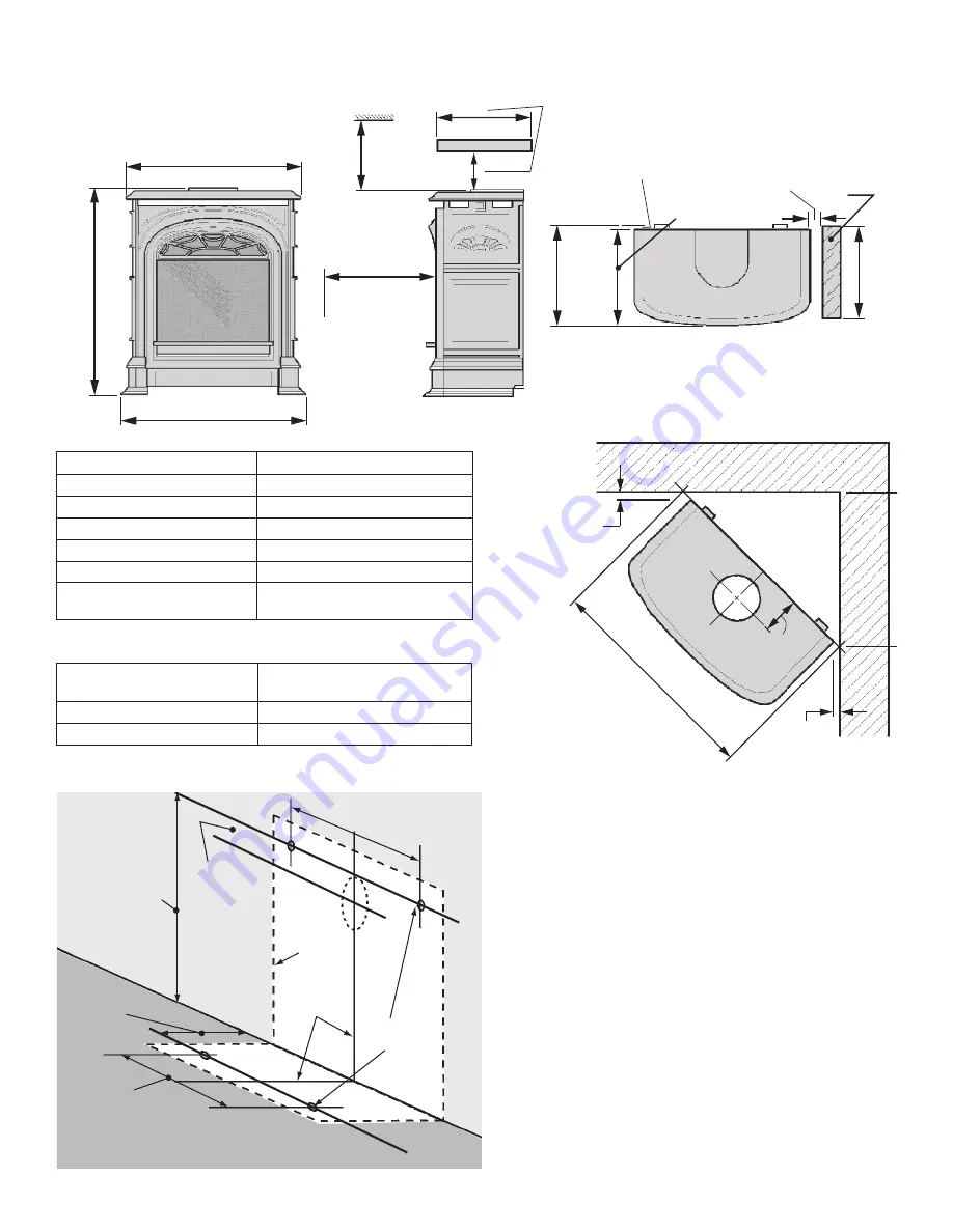
Dimensions & Clearances
Mantel Depth “A”
Min. Clearance “B”
Up to 7”
4”
Above 7” up to 8”
5”
Above 8” up to 9”
7”
Above 9” up to 10”
8”
Above 10” up to 12”
9”
More than 12”
9” +extra 1” for every 1” depth
above 12”
Mantel Leg Projection “D”
Min. Clearance from
Appliance Side “E”
Up to 8”
0”
More than 8”
6”
1-1/4”
(32 mm)
min. from
casting Top
to wall
Allow
more
space as
necessary
for venting
components
28”
(711 mm) min.
1-1/4”
(32 mm)
min. from
casting Top
to wall
3-3/4”
(95 mm)


