DSBA3400 • Rév. 09/06/2020
30
EN
VS model:
No declutching is required, the hand wheel has simply to be turned (appendix p.47 mark 10).
The end mechanical stops are pre-set to 90° and stuck (Tubetanche Loctite 577 or equivalent). It is possible to
adjust then by moving the 2 screws M8 (appendix p.47 mark 18) but you need to stick them again in order to en-
sure a proper sealing.
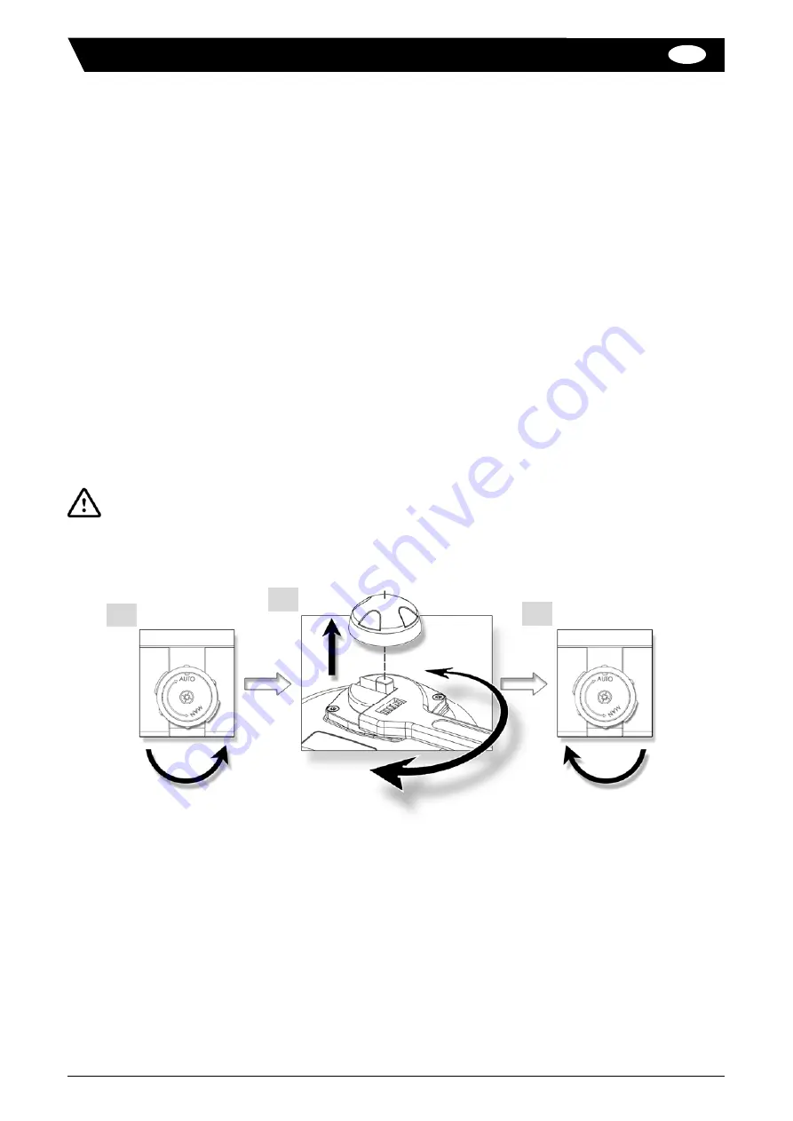
1. Turn the knob to position MAN (counter-clockwise) and hold it in position.
2. Turn the outgoing drive shaft of the actuator with the help of an adjusting spanner.
3. In order to re-engage the reduction, release the knob (spring return).
The priority functioning mode of this actuator is electric. Be sure than the power supply is switched off
before using the manual override.
VR model:
1
2
3
VR model:
Possible fixations : F05 (4xM6 with Ø50) and F07 (4xM8 with Ø70), star 17, depth 19mm.
Necessary height above the valve for the mounting of the actuator : H=300mm.
VR model:
Possible fixations : F07 (4xM8 with Ø70) and F10 (4xM8 with Ø102), star 22, depth 25mm.
Necessary height above the valve for the mounting of the actuator : H=360mm.
Mounting / disassembly of the cover and position indicator
For the wiring and setting of the actuator, it is necessary to remove the cover.
Mounting of the cover (appendix p.47 mark 2) : make sure that the seal ring (appendix p.47 mark 7) is correctly
placed in its position, mount the cover and tighten the 4 screws M6 (appendix p.47 mark 3, torque : max. 6Nm).
Mounting of the position indicator for VR (appendix p.47 mark 1) : fit the indicator onto the outgoing axle (according the dia-
gram p.28).
Mounting of the position indicator for VS (appendix p.47 mark 1) : mount the seal ring and the indicator then the window with
the 4 screws M4 (according the diagram p.28).
Emergency manual override
Mounting on valve

