DSBA3400 • Rév. 09/06/2020
40
EN
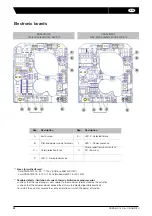
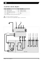
POSI: electric diagram
Rep.
Description
Rep.
Description
FC0
Open limit switch
FC1
Auxiliary limit switch 1
FCF
Close limit switch
FC2
Auxiliary limit switch 2
D1/D2 Failure report Terminal strip (24V DC / 3A max)
For GPS models, refer to the section p.44 et 45.
The terminal temperature can reach 90°C.
The used wires must be rigid (feedback voltages: 4 to 250V AC/DC).
For a use with a long power supply wiring, the induction current generated by the wires mustn't be higher than
1mA.
The control voltage must be S.E.L.V. (Safety Extra Low Voltage).
No common earth/ground connexion between the control (input and output signal) and the alimentation. (Type 0-20
or 4-20mA : 5V DC max.)
The card resolution is 1°
10 kOhm input impedance if control with voltage (0-10 V) and 100 Ohm input impedance if control with current
(0-20 mA or 4-20 mA)
i
F
EED
B
A
C
K
SIGN
AL
SETPO
IN
T
SIGN
AL
Motor
=
SNAA480000
18
17
16
15
14
13
+
-
-
+
4-20mA / 0-10V
3
2
1
TP/PE
N
-
Ph
+
SNAA690000
9
8
6
4
FCF
FC0
A
+
—
~
~
FC2
FC1
C
A
B
7
5
CO
MMO
N FC1
CO
MMO
N FC2
FEE
D
BACK FC1
FEE
D
BACK FC2
17
18
D2
D1
100V-240V 50/60Hz
(100V-350V DC)
15V-30V 50/60Hz
(12V-48V DC)
FEEDBACK
POWER SUPPLY
4

