Service and Installation Manual
For warranty service, call 1-888-VALPRO8 / 1-813-502-0300
7
OPERATION
Do not throw items into the storage area. Failure to heed these recommendations
could result in damage to the interior of the cabinet.
Refrigerated cycle
Refrigerators:
During the refrigeration cycle, the evaporator fans wilt run continuously even when one or
more doors are open. The door switch will activate the lights when opened.
1.
Every 6 hours, the unit will turn off and to allow the evaporator coil to defrost. The controller now
displays defrost symbol. When the coil temperature reaches 41°F or after 20 minutes of defrost, the unit
will turn on again.
2.
Anti-condensation heaters on door frames work in conjunction with the compressor.
3.
The factory setting for the temperature range is 34°F to 38° F.
Freezers:
During the refrigeration cycle, the controller supplies power to the condensing unit and
evaporator fan motors. The evaporator fans will run at any time when the evaporator coil temperature is
below 54° F. They will also keep running when door is open but cycle off during a defrost period. The door
switch will activate the lights when opened.
1.
Every 6 hours, the unit will turn off and electric heater will turn on to defrost. The controller now
displays the defrost symbol. When the coil temperature reaches 45°F or after 20 minutes of defrost, the
unit will turn on again.
2.
Anti-condensation heaters on door frames work in conjunction with the compressor.
3.
The factory setting for temperature range is -7
to -3°F
SOLID-STATE THERMOSTAT DESCRIPTIONS
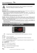
1. FRONT PANEL COMMANDS
To display target set point; in programming mode it selects a parameter or confirm an
operation.
To start a manual defrost
To view the last alarm occurrence; in programming mode it browses the parameter
codes or increases the display value
To view the last alarm occurrence; in programming mode it browses the parameter codes or
decreases the display value
KEY COMBINATION
To lock & unlock the keyboard
To enter in programming mode
To return to the room temperature display
CAUTION
To switch the instrument off.
Summary of Contents for VP19F-HC
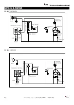
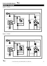
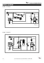
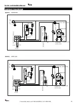
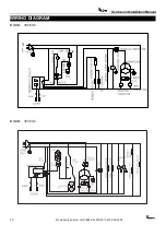
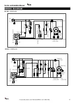
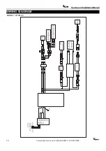
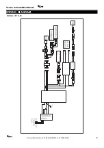
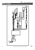
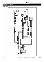
Page 28: ...Service and Installation Manual WIRING DIAGRAM MODEL VP1FG HC ...
Page 30: ......


