Manuale di Installazione e Manutenzione unità di recupero calore ad altissima efficienza -
Very high efficiency heat recovery unit
pag. 18
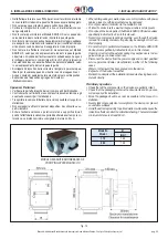
3.5 MONTAGGIO A SOFFITTO
• Posizionare l’unità su di una struttura solida adeguata al peso della
macchina; interporre sempre opportuni sistemi flessibili e smorzanti
tra unità e struttura di supporto. Evitare le connessioni rigide, fonte
di trasmissione meccanica delle vibrazioni.
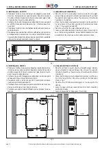
• Verificare che i punti di fissaggio siano allineati ed in piano e segnarli
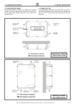
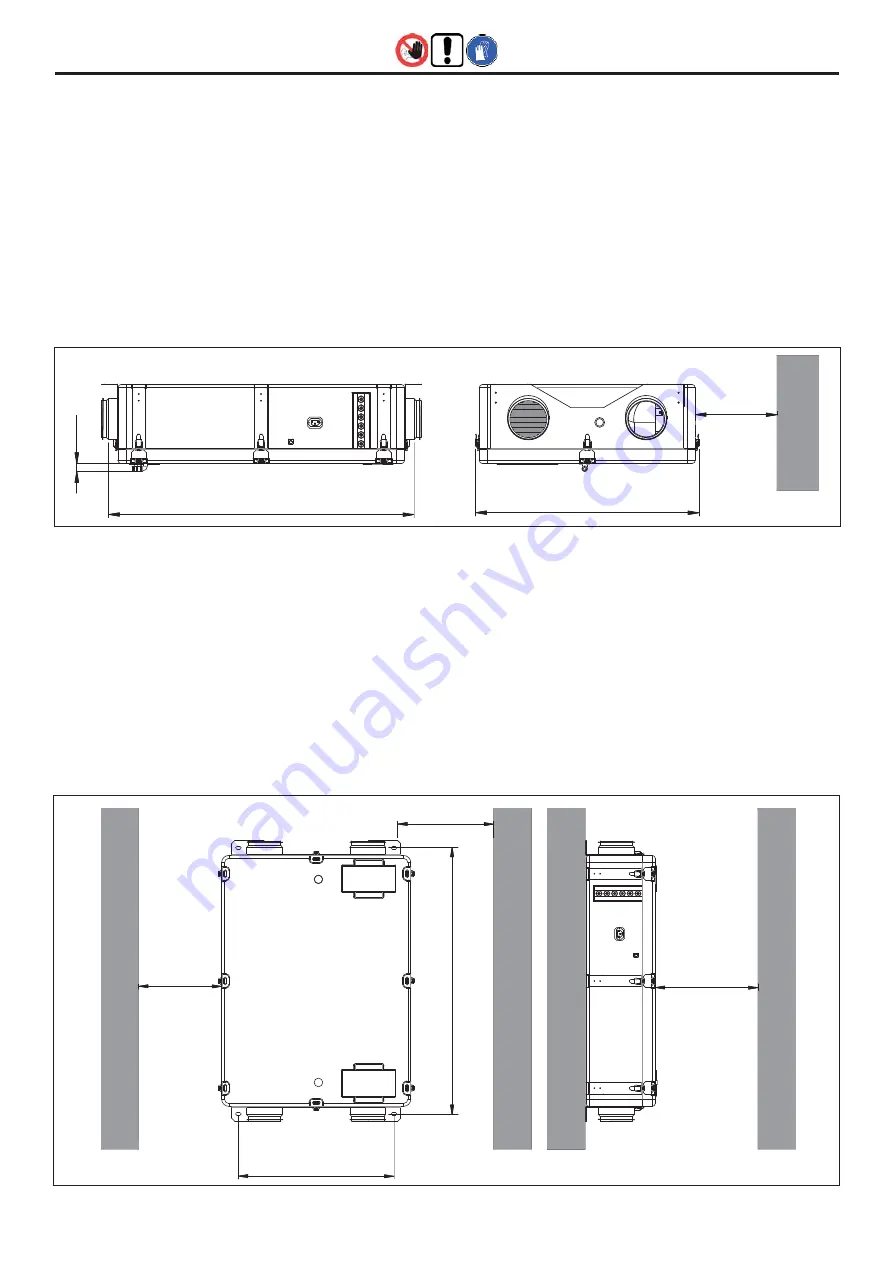
sul soffitto in base alle quote indicate in fig. 1. Utilizzare tasselli an-
coranti Ø8.
• Posizionare l’unità in modo che il deflusso della condensa possa av-
venire facilmente.
• Prevedere uno spazio laterale e inferiore sufficiente per le operazioni
di collegamento e manutenzione; in caso di controsoffitti di chiusura,
ricavare botole di opportuna dimensione per garantire l’accessibilità
alla macchina ed agli eventuali accessori a canale.
fig. 1
922
300
22
680
500
300
539
300
922
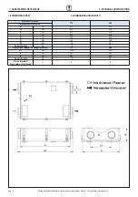
fig. 2
3 - INSTALLAZIONE E MESSA IN SERVIZIO
3 - INSTALLATION AND START UP
3.5 MOUNTING OF HORIZONTAL
• Place the unit over a solid support structure, suited to unit weight;
always interpose proper anti-vibration devices between the unit and
the supports. Avoid rigid connections, they are source of mechanical
transmission of vibrations.
• Check that the bases are aligned and coplanar; sign the position of
the fixing points on the ceiling, according to the dimensions shown
on fig. 1. Use expansion dowel
Ø
8.
• Place the unit so that the water drainage can be easy.
• Leave an accessible lateral and lower gap space for servicing; in
case of false-ceiling installation, make suitable trapdoors to ensure
accessibility to the machine and its possible duct accessories.
3.6 WALL MOUNTING OF VERTICAL
• Place the unit close to a wall suited to unit weight; always interpose
proper anti-vibration devices between the unit and the supports.
Avoid rigid connections, they are source of mechanical transmission
of vibrations.
• Check that the fixing points are aligned and coplanar; sign the posi-
tion of the fixing points on the wall, according to the dimensions
shown on fig. 2.
• Place the unit so that the water drainage is on the lower part of the
machine.
• Leave the upper and lower needed space for all duct connections
and their bend sizes.
• Leave an accessible front gap space for servicing.
3.6 MONTAGGIO A PARETE
• Posizionare l’unità su di una parete adeguata al peso della macchina;
interporre sempre opportuni sistemi flessibili e smorzanti tra unità e
struttura di supporto. Evitare le connessioni rigide, fonte di trasmis-
sione meccanica delle vibrazioni.
• Verificare che i punti di fissaggio siano allineati ed in piano e segnarli
sulla parete in base alle quote indicate in fig. 2.
• Posizionare l’unità in modo che il punto di scarico della con.densa
risulti nella parte inferiore dell’unità.
• Prevedere il necessario spazio superiore ed inferiore per le connes-
sioni aerauliche ed per i loro ingombri di curva.
• Prevedere uno spazio frontale sufficiente per le operazioni di manu-
tenzione.


