Valtir.com
17
Revision D February 2023
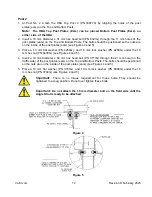
4. At Post location 4, fasten the Standard Guardrail (PN 10629G) and U-Bracket (PN 33461G) to
the 2000 mm C120 Post (PN 6183G) using a 16 mm x 50 mm Guardrail Post Bolt (PN
3400G), a rail nut (PN 3340G), and a flat washer (PN 3300G) (see Figure 6). The washer is
positioned between the post and the nut.
5. At Post location 3, splice the 4 m Anchor Guardrail (PN 29G) to the 4 m Standard Guardrail (PN
10629G) attached in Step 3 (above) using eight (8) 16 mm x 32 mm Guardrail Splice Bolts (PN
3360G) and rail nuts (PN 3340G).
Fasten a U-Bracket (PN 33461G) to the 2000 mm C120 Post (PN 6183G) using a 16 mm x50
mm Guardrail Post Bolt (PN 3400G), a rail nut (PN 3340G), and a flat washer (PN
3300G). The washer is positioned between the Post and the nut (see Figure 6)
Important:
Do not bolt the Rail Panels to Post 3.
6. At Post location 2, fasten the 4 m Anchor Guardrail (PN 29G) to the HBA Top Post 2 (PN
33877A) using a 16 mm x 50 mm Guardrail Post Bolt (PN 3400G), a rail nut (PN
3340G), and a flat washer (PN 3300G) (see Figure 1). The washer is positioned between
the post and the nut.
7. At Post Location 1, the 4 m Anchor Guardrail (PN 29G) must
not
be attached to the HBA Top
Post 1 (PN 33462A).
Important:
Do not bolt the Rail Panel to Post 1.
Cable Anchor Assembly
The Cable Anchor Bracket (PN 704A) is secured to the 4 m Anchor Guardrail (PN 29G) by inserting
the protruding hooks on the Cable Anchor Bracket (PN 704A) into the square slots in the Anchor
Guardrail (PN 29G). The Cable Anchor Bracket (PN 704A) is locked into place by pulling the bracket
towards the front end of the system.
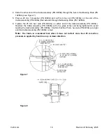
1. Slide one end of the Cable Assembly (PN 3000G) into the Cable Anchor Bracket (PN 704A) and
the other end through the space between the HBA Top Post 1 (PN 33462A) and HBA Bottom
Post 1 (PN 33873A) (see Figure 7).
2. Place a 25 mm f at washer (PN 3900G) and a 25 mm hex nut (PN 3910G) on the end of the
Cable Assembly (PN 3000G) that extends through the Cable Anchor Bracket (PN 704A). Turn
the nut until at least 2 threads are completely through the nut.
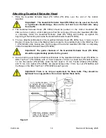
3. Place the Bearing Plate (PN 19258A) [125 mm dimension up and the 76 mm dimension
down] in front of the HBA Top Post 1 (PN 33462A) and HBA Bottom Post 1 (PN 33873A) (see
Figures 7 and 8).
Note:
The tabs on the Bearing Plate (PN 19258A) rest on top of the HBA Top Post plates
(ears)
.
Warning:
Any grout, backfill, or other materials (such as concrete, asphalt, or soil)
must be low enough so as not to obstruct, constrain, or otherwise engage the bearing
plate. Failure to eliminate the interaction of soil or materials with the bearing plate will
hinder the performance of the EURO-ET™ system and could result in serious injury
or death in the event of a collision.
Summary of Contents for EURO-ET END TERMINAL
Page 1: ...PN 619489 REVISION D FEBRUARY 2023 EURO ETTM END TERMINAL PRODUCT DESCRIPTION ASSEMBLY MANUAL...
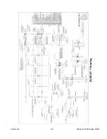
Page 24: ...Valtir com 23 Revision D February 2023 EURO ET Drawing...
Page 25: ...Valtir com 24 Revision D February 2023 Notes...
Page 26: ...Valtir com 25 Revision D February 2023 Notes...


