background image


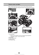
Tractor serial numbers

When ordering spare parts or service, give the model indication and serial

numbers and, in some cases, the engine, front axle, cab and transmission numbers.

N142 V AC15.2

V12140

1

3

2

5

4

GUID-CC7D465F-65A4-4155-85EE-FB823433D27F

1. Type plate EEC

Model = model indication used by service/spare part department

Identification number = tractor serial number

2. Cab number

3. Tractor serial number

4. Engine number

5. Front axle number

- 2 -

Find manuals at https://best-manuals.com

Summary of Contents for Versu N2 Series

Page 1: ...Operator s Manual N2 Series Versu...

Page 2: ...Find manuals at https best manuals com...

Page 3: ...laws and regulations even if they are not specifically pointed out in this manual The manual contains detailed instructions for operating servicing and maintaining the tractor Alternative equipment in...

Page 4: ...xle cab and transmission numbers N142 V AC15 2 V12140 1 3 2 5 4 GUID CC7D465F 65A4 4155 85EE FB823433D27F 1 Type plate EEC Model model indication used by service spare part department Identification n...

Page 5: ...he left side of the display 24 2 2 4 Indicator lights on the right side of the display 25 2 3 Controls on the right hand side 26 2 3 1 Tractor terminal 26 2 3 2 Driving controls 27 2 3 3 Linkage 28 2...

Page 6: ...railer hitch light 68 3 4 5 Using the cab light 69 3 5 Using notification devices 70 3 5 1 Using the direction indicators 70 3 5 2 Using the horn 70 3 5 3 Using the rotating warning light 71 3 5 4 Usi...

Page 7: ...ng 105 3 8 14 Automatic traction control 106 3 8 15 Using the automatic traction control 106 3 8 16 Using the hydraulic front suspension 108 3 8 17 Calibrating the hydraulic front suspension 109 3 8 1...

Page 8: ...1 5 General information drive view symbols 138 3 11 6 Pop up views 140 3 11 7 Entering the large drive view 141 3 11 8 Split drive view 141 3 11 9 Entering the split drive view 141 3 11 10 Changing th...

Page 9: ...r valves 1 and 2 and front valves 1F and 2F 179 3 14 5 Controlling the rear valve 1 from rear mudguard push buttons 180 3 14 6 Controlling the auxiliary hydraulics rear valves 3 and 4 and the front va...

Page 10: ...3 3 21 1 3 Latching the trailer hitch 225 3 21 2 Agricultural drawbar 226 3 21 3 Scharm ller towing device 227 3 21 3 1 Adjusting the jaw height 227 3 21 3 2 Attaching to the mechanical jaw 229 3 21 3...

Page 11: ...ng the air conditioning compressor belt 264 4 7 3 12 Adjusting the air compressor belt 264 4 7 3 13 Changing the air conditioning compressor belt 265 4 7 3 14 Changing the multi grooved fan belt and t...

Page 12: ...8 1 2 Tyre parameters 307 4 8 1 3 Calibrating speed sensors 308 4 8 2 Track widths 310 4 8 2 1 Agricultural front axle track widths 310 4 8 2 2 Industrial front axle track widths 311 4 8 2 3 Rear axle...

Page 13: ...and pressures 342 6 4 3 Rear axle tyre loadings and pressures 343 6 5 Stud dimensions and spacing for wheel discs 344 6 6 Track widths 345 6 6 1 Rear track widths 345 6 6 2 Front track widths 345 6 7...

Page 14: ...liary hydraulics 354 6 13 3 2 Counter pressure when using the return connection for auxiliary hydraulics 354 6 13 4 Rear linkage 355 6 13 4 1 Maximum lifting force on the whole lifting area 355 6 13 4...

Page 15: ...icates a potentially hazardous situation that if not avoided could result in death or serious injury CAUTION Indicates a potentially hazardous situation that if not avoided may result in minor injury...

Page 16: ...ck the brake pedals together whenever individual wheel brakes are not required and always when driving on the road Extensive repairs to the braking system should be undertaken only by an authorised Va...

Page 17: ...extra equipment Roof hatch extra equipment 1 2 GUID E522C473 E223 48DF BC14 03DCD1490CD2 1 Handle 2 Gas spring Open the hatch by pushing the handle forward and pushing the hatch upward To open the ha...

Page 18: ...e rear linkage When the indicator light is not lit the auxiliary hydraulics is deactivated DANGER To prevent accidental auxiliary hydraulics control movements always turn off the auxiliary hydraulics...

Page 19: ...ock Use the differential lock only when running on loose or slippery ground Hydraulic fuel pressure Do not attempt to locate a leak in the hydraulic system or attempt to close a leak using any part of...

Page 20: ...ine IMPORTANT Do not brake continuously as the brakes may overheat IMPORTANT Do not let the engine overrun to avoid damage to the engine NOTE If the speed is too high a speed warning is shown on the i...

Page 21: ...hen the tractor is towing a trailer the brake pedals must be locked together The brakes are not to be used individually for steering WARNING When using a trailer make sure that the hitch latch is lock...

Page 22: ...DANGER You may be held responsible for any resulting accidents Do not allow children untrained or unqualified persons to operate your tractor They could injure themselves or someone else 1 2 4 10 Fire...

Page 23: ...ractor pedals are positioned as follows 1 4 2 5 3 GUID B9DB5C5F FE87 4414 8461 21CBE5754B55 1 Clutch pedal 2 Locking pedal for steering wheel inclination 3 Latch for brake pedals 4 Brake pedals 5 Acce...

Page 24: ...over switch 8 Proline instrument panel display setting switch 9 Upper headlights extra equipment 10 Multifunctional lever 11 Ignition switch 12 Lever for adjusting steering wheel position 13 Electric...

Page 25: ...ture 2 2 2 Symbols on the Proline instrument panel display The Proline instrument panel display have fixed views and views that can be selected by the operator Fixed view symbols The fixed views are t...

Page 26: ...side of the display GUID 2DD1EF78 31AF 457A A2AB 4B2CAD4A6378 Indicator light Indication GUID 32CAE5D4 C71C 4D8B A41F 2E1DE50F1ED4 Direction indicator light for second trailer green If one of the bul...

Page 27: ...C77 7CDB 4FB5 AF3A BEFDF3417EB1 Battery charging indicator light 2 2 4 Indicator lights on the right side of the display CRUISE F R S T O P GUID 0465EB98 1ABC 4D9F 99B4 4EE9E99E94E7 Indicator light In...

Page 28: ...he creeper gear is engaging GUID 533CED2D D3E0 4488 8590 A1E859BA91C5 Differential lock indicator light The light is lit yellow to indicate that the differential lock is engaged GUID 70C6E3BD C691 481...

Page 29: ...r wheel drive 4WD 5 Switch for differential lock 6 Switch for front suspension alternative equipment 7 Switch for shifting automatics 8 Switch for automatic traction control 9 STOP indicator light red...

Page 30: ...ve balance control including slip control system 6 Lift lower push buttons 7 Lift lower indicator lights 8 Drive balance control light 9 Slip control light 10 Switch for trailer hitch latch hydraulic...

Page 31: ...This as a preview PDF file from best manuals com Download full PDF manual at best manuals com...

Reviews: