background image

No.

Description

Qty

No.

Description

Qty

No.

Description

Qty

No.

Description

Qty

1

Bolt

1

24

O-ring 1.7×2

1

47

spring washer 4

2

70

Srew M4×6

2

2

Deflector Spring

1

25

Step Pin

1

48

Elastic spacer(Quick

unloading)

1

71

Bolt M4×6

2

3

Air Deflector

1

26

Slide Stand

1

49

Cover plate(Quick

unloading)

1

72

fixed seat

1

4

Bolt M5×20

6

27

Compressed Spring

1

50

Sticker Plate(Quick

unloading)

1

73

palt washer 4

2

5

Spring Washer 5

6

28

E-ring 6

1

51

Driver Guide(Quick

unloading)

1

74

Bolt M4×20

1

6

Cylinder Cover

1

29

TUV guide stand asse

1

52

Bolt M4×14

2

75

Rubber Handle

1

7

O-ring 13.7×2.4

1

30

TUV Adj. Nut

1

53

Movable Magazine

1

76

O-ring 36.3×3.55

1

8

sealing Washer

1

31

Nut M4

3

54

Pin 1.5×10

1

77

End Cap

1

9

Compressed Spring

1

32

Pusher Spring

1

55

Inlay Slice

1

78

Air Inlet Plug

1

10

Switch Valve

1

33

Steel ball Dw=2

1

56

Fixed Magazine

1

79

Air Inlet Plug case

1

11

bumper Washer

1

34

Safety frame assembly

Quick unloading

1

57

Indicate Label

1

80

O-ring 2.4×1.6

1

12

O-ring 31.2×2.5

1

35

Rectangular Washer

1

58

Magazine Label

1

81

Pin 2.5×10

1

13

O-ring 24.8×3.5

1

36

Trigger Valve Guide

1

59

Slice

1

82

Pin 2.0×10

1

14

sealing spacer

1

37

trigger stem Spring

1

60

Pipe

1

83

Positioning circlip

1

15

Collar

1

38

Trigger Valve Stem

1

61

Fixed Seat

1

84

Pin 3×16

1

16

O-ring 41.7×3

1

39

O-ring 2.5×1.5

2

62

Compressed Spring

2

85

Guide sleeve

1

17

O-ring 26.2×2.4

1

40

Trigger Valve Seat

1

63

Pusher Pipe

2

86

Bolt M4×8

1

18

Cylinder

1

41

O-ring 11.2×2

1

64

Tip Stand

1

87

Bracelet cover

1

19

O-ring 21×3

1

42

trigger handle Spring

1

65

Compressed Spring

1

88

Pin 3×26

2

20

Main piston

1

43

Pin 2.5×16

1

66

Spacer

1

89

Bolt M4×14

2

21

Bumper

1

44

Safety Spacer(Quick

unloading)

1

67

Support Seat

1

Oil pot

1

22

Gun Body

1

45

Trigger

1

68

Bolt M4×38

1

Hex wrench M4/3mm

1

23

Rubber Washer

1

46

Tensioning trigger assembly

1

69

Pin

1

Hex wrench M5/4mm

1

Assy.


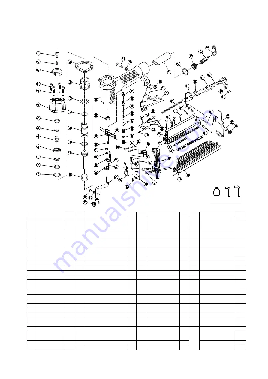
  Explode Drawing &Spare parts list 

Issue Date:2018.05.24

Version No:C/0

Summary of Contents for SF5040E

Page 1: ...s and operating Instructions carefully before starting the product Keep this Manual for future reference Residual Risks Even when the tool is used as prescribed it is not possible to eliminate all residual risk factors The following hazards may arise in connection with the tool s construction and design ...

Page 2: ...ing pressure 60 to100 PSI 4 to 7 bar Maximum pressure 120PSI 8 3bar Air consumption 0 038CF CYCLE 90PSI Air inlet 1 4 6 35mm Dimensions 55x245x250mm Weight 1 48kgs 3 26lb SCFM Standard Cubic feet per minute the volumetric flow rate of air corrected to standardized conditions of temperature and pressure Environmental Responsibilities Please recycle unwanted materials instead of disposing of them as...

Page 3: ...s Use a minimum of 25 7 6m of hose to connect the tools to the compressor Failure to comply will result in serious injury or loss of life Risk of electric shock Do not expose a compressor to rain Store it indoors Disconnect the compressor from power source before servicing Compressor must be grounded Do not use grounding adaptors Risk of personal injury Do not direct compressed air from the air ho...

Page 4: ...afety rules regulations and conditions when using the tools Carry the tool by the handle only Do not carry the tools with a finger on the trigger Do not carry the tool by the hose magazine or any other parts Do not use the tool near or below freezing temperatures as doing so may cause tool failure Do not store the tool in a freezing environment to prevent ice formation on the operating valves of t...

Page 5: ...AGRAM IMPORTANT INFORMATION Compatible compressors GUIDELINES FOR PROPER USE AND OPERATION Be sure to use a proper air compressor with air powered tools General use This nailer drives 18Ga Brad Nails 5 8 2 and 18Ga Crown staples 5 8 1 5 8 If feature a die cast aluminum housing and a comfortable handle for optimal control and comfort even during extended use It is well balanced for stability and er...

Page 6: ...onnections in the air supply system are sealed in order to prevent air from leaking NO Description NO Description NO Description 1 VALU AIR Air powered 2 in 1 nailer 4 Air Hose 7 Filter 2 Quick connector 5 Lubricator 8 Cut off valve 3 Quick coupler 6 Regulator 0 to 8 3 Bar 9 Air compressor WARNING Potential hazard that could result in serious injury or loss of life Do not use the tool if it is not...

Page 7: ...used Figure 4 Loading nails into magazine 4 Slide the staples or brads all the way down to the nose of the nailer stapler For brad nail Insert a stick of fasteners into the magazine rail D Make sure the pointed ends of the fasteners are resting on the bottom ledge of the magazine when loading For staples set a stick of fasteners on the top of magazine 5 Push the magazine toward the nose of the nai...

Page 8: ...e nail staple drove into the wood far enough continue with your intended operations If the nail staple either went too far or not far enough then go to the Adjusting Depth sub section on this page DANGER Potential hazard that could result in serious injury or loss of life Disconnect the tool from the compressed air source before loading fasteners Do not point the tool towards the operator or other...

Page 9: ...gazine until the catch lever locks To clear a jammed nail from the discharge area 1 DISCONNECT NAILER STAPLER FROM THE AIR SUPPLY 2 Unlock the catch lever and pull the magazine pusher back completely 3 Remove the nail staple stick from the magazine 4 Pull up on the latch and open the jam release 5 Insert a flat blade screwdriver into the driving mechanism and push the driver mechanism back freeing...

Page 10: ... the new piston and apply a thin film of the nailer stapler lubricating oil on the O ring 10 Insert the new piston in the cylinder Make sure that the grooves on the piston shaft line up with those on the guide at the bottom of the cylinder The new piston should easily slide into the cylinder DO NOT force the piston into the cylinder If the piston is not easily inserted double check the alignment o...

Page 11: ... Check and replace O ring 2 Check and replace 3 Check and replace trigger valve stem seal or O ring Air leak near bottom of tool 1 Loose screws 2 Worn or damaged O rings or bumper 1 Tighten screws 2 Check and replace O rings or bumper Air leak between body and cylinder cap 1 Loose screws 2 Worn or damaged O rings or seals 1 Tighten screw 2 Check and replace O rings or bumper Blade driving fastener...

Page 12: ...e 1 11 bumper Washer 1 34 Safety frame assembly Quick unloading 1 57 Indicate Label 1 80 O ring 2 4 1 6 1 12 O ring 31 2 2 5 1 35 Rectangular Washer 1 58 Magazine Label 1 81 Pin 2 5 10 1 13 O ring 24 8 3 5 1 36 Trigger Valve Guide 1 59 Slice 1 82 Pin 2 0 10 1 14 sealing spacer 1 37 trigger stem Spring 1 60 Pipe 1 83 Positioning circlip 1 15 Collar 1 38 Trigger Valve Stem 1 61 Fixed Seat 1 84 Pin 3...

Reviews: