background image


Page 9 

S

TEM

 R

OTATION

 D

IRECTION


AND

 V

ALVE

 P

OSITION

 I

NDICATION


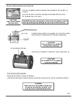
Typical valve hand wheels and levers require 
80 lbf. (335N) of handle force to operate. 

80 lbs. to 

CLOSE 

Lever operated are shown to be open when 
the handle lies on the same axis as the valve 
bore. The valve indicated closed when the 
handle is at 90

o

 to the valve bore. 

A

CTUATOR

 O

PERATION


Valve actuators must be installed, operated and maintained as per their manufacturer’s written  
instruction. In the event of a conflict between these instructions and those contained in this manual an 
authorized ValvTechnologies distributor or to ValvTechnologies Houston facility should be contacted. 


The lubricant of worm gear actuators should be inspected every three months and be replenished or 
replaced if required. 

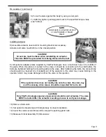
On actuated and gear-operated valves an arrow 
shows the valve position. 

The stem, gland and ball (and in some instances the 
drive sleeve) bear markings as shown to the left. The 
marks will line up on the left of a closed valve, when 
looking down on the stem and facing downstream. 


All ValvTechnologies ball valves (unless spe-
cifically stated) are operated clockwise to 
close and counter-clockwise to open.


CAUTION!  During disassembly 
particular care should be taken 
not to damage mating, packing, 
or sealing surfaces.


CAUTION!  Packing must be re-
placed if gland nuts are loose. 
Only approved ValvTechnolo-
gies packing shall be used.


MAINTENANCE 

WARNING! 

DISASSEMBLY AND REPAIR OF VALVTECHNOLOGIES VALVE 


ASSEMBLIES BY UNAUTHORIZED PERSONNEL MAY BE HAZARDOUS AND 


NEGATE WARRANTIES. 

D

ISASSEMBLY


Summary of Contents for V1 Series

Page 1: ...Page VALVTECHNOLOGIES INC BALL VALVE Installation and Operations Maintenance Manual...

Page 2: ...8 LUBRICATION 8 TORQUE TABLES 8 STEM ROTATION POSITION 9 ACTUATORS 9 IV MAINTENANCE 9 DISASSEMBLY 9 REPAIR REWORK 10 11 BELLVILLE SPRING HEIGHTS 11 12 RE ASSEMBLY 12 13 INSTALLING ACTUATOR 13 PRESSURE...

Page 3: ...l is to describe procedures that will ensure safe and successful installation operation and maintenance of the metal seated ball valve assuming a trouble free service life Difficulties encountered in...

Page 4: ...oad Belleville Spring Upstream Seat Guide Body Seal Hard coated Integral Seat Hard coated Ball High Load Belleville Spring Actuator Mounting Pad Live Loaded Gland Springs Gland Gland Packing Actuator...

Page 5: ...ecial Port ACTUATION Lever Operated LV Cast 150 600 Forged 900 Up LC Cast 900 Up LF Forged 150 600 Bare Stem BS Cast 150 600 Forged 900 Up BC Cast 900 Up BF Forged 150 600 VALVE SIZE Nominal Valve Siz...

Page 6: ...h electric actuators should be cycled to the mid stroke position before cycling under power WARNING VALVES SHOULD NEVER BE USED AS A STRUCTURAL MEMBER ORIENTATION CAUTION Valves must be installed with...

Page 7: ...t insulating or stress relieving technique may damage the valve and void the warranty CAUTION Valve must be OPEN during welding CAUTION Valve insulation is prohibited during stress relieving Only insu...

Page 8: ...9 210 285 1 3 8 35 950 1288 290 393 1 1 2 38 1250 1695 370 502 1 5 8 41 1600 2169 480 651 1 3 4 44 2060 2793 500 678 1 7 8 48 2500 3390 750 1017 2 51 3000 4067 900 1220 3 76 10300 13965 3100 4203 3 1...

Page 9: ...actuators should be inspected every three months and be replenished or replaced if required On actuated and gear operated valves an arrow shows the valve position The stem gland and ball and in some...

Page 10: ...iding excessive force remove the entire actuator assembly 6 Remove body seal or gasket depending upon valve design 7 Remove body gasket if applicable 8 Remove ball after mark ing orientation and prote...

Page 11: ...e Ranges Other Valve Components In general these may be cleaned and returned to service If rework is required consult ValvTechnologies Engineering Department The ball is lapped to the end cap using 3...

Page 12: ...ats are parallel to bore 2 Stem shall be inserted through the stem hole from the body cavity side NOTE Mark on top of stem should be on the left of the valve when looking down on the stem and facing d...

Page 13: ...After tightening the bolts the concentricity should again be checked Any misalignment of the operator to the valve may cause binding in the operator which may cause damage to either the valve or the o...

Page 14: ...4 068 1 727 1 1 2 38 045 1 143 068 1 727 2 1 8 54 048 1 219 071 1 803 3 1 16 78 078 1 981 105 2 667 4 1 16 103 095 2 413 125 3 175 5 1 8 130 120 3 048 145 3 683 6 1 16 154 145 3 683 178 4 521 8 1 16 2...

Page 15: ...ecause of access use alternative method shown to the left Belleville Spring Standoff 19 Measure Belleville Spring height Refer to Table 3 for acceptable height range If height is out of specification...

Page 16: ...m SEAT BALL GAP in mm MINIMUM MAXIMUM 5 8 16 N A 087 2 210 1 1 8 29 N A 075 1 905 1 1 2 38 032 813 046 1 168 2 1 8 150 300 54 N A N A 2 1 8 600 4500 54 040 1 016 056 1 422 3 1 16 78 053 1 346 067 1 70...

Page 17: ...s should re main precisely parallel Failure to do so may result in a faulty seal Torque in a star pattern to 1 3 of torque value listed in Table 1 Then torque in a star pattern to 2 3 of torque value...

Page 18: ...will not rotate or operate 1 Actuator has failed 2 Valve packed with debris 3 Stem key has sheared 4 Ball seat gap incorrect 1 Replace or repair actuator 2 Cycle flush valve to re move debris 3 Deter...

Page 19: ...es below RECOMMENDED SPARE PARTS FOR V1 SERIES BALL VALVES CLASS PART DESCRIPTION QTY SAME TYPE SIZE PERCENT COVERAGE A Gland Packing Gland Load Springs 1 3 70 B Body Gasket Metal Belleville Spring 1...

Page 20: ...5 TEXAS ValvTechnologies Inc 5904 Bingle Road Houston Texas 77092 U S A Telephone 713 860 0400 Facsimile 713 860 0499 E mail sales valv com Web www valv com Celtex Industries White Oak Texas 903 297 8...

Reviews: