


VAMP Ltd
Generator protection relay
Technical description
VAMP 210
VM210.EN004
Vamp 24h support phone: +358 (0)20 753 3264
7
2.2.
Protection relay functions
2.2.1.
Overcurrent protection (50/51)
The three-phase overcurrent unit comprises two separately
adjustable overcurrent stages, stage I> and stage I>>.
The overcurrent unit measures the fundamental frequency
component of the phase currents.
The low-set stage I> can be configured for definite time or
inverse time operation characteristic. Four characteristic curve
sets according to the standard IEC 60255-3 are available: NI
(normal Inverse), VI (Very I.), EI (Extremely I.) and LTI (Long
Time I.). Stage I>> is configured for definite time operation
characteristic (DT).
The overcurrent unit may provide main short circuit protection
for generators in applications, where no differential relay or an
underimpedance relay is used.
For large generators the overcurrent unit provides back-up
protection for the differential relay or underimpedance relay in
e.g. network disturbance situations, should the disconnection
not be fast enough from the point of view of the generator
protection.
In order to secure operation of the overcurrent unit also at
internal generator faults or close by faults the phase currents
are to be measured with current transformers installed on the
generator neutral side.
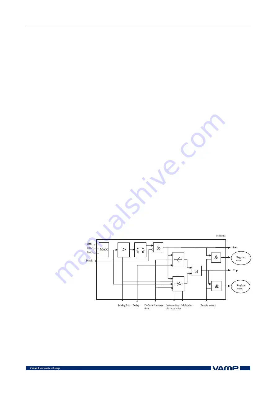
Figure 2.2.1-1 shows a functional block diagram of the I> stage
of the overcurrent unit.
Figure 2.2.1-1 Block diagram of the three-phase overcurrent stage I>.


