PRINTED IN THE U.S.A.
PAGE 3
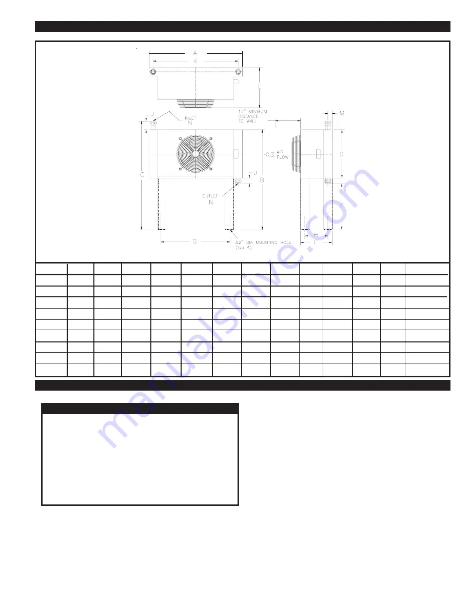
SPECIFICATIONS AND DIMENSIONS
SECTION 3
3.2 DIMENSIONS AND COMPONENT LOCATIONS
N
IN/OUT
1" NPT
1" NPT
1-1/2" NPT
1-1/2" NPT
1-1/2" NPT
1-1/2" NPT
1-1/2" NPT
2" NPT
2" NPT
INSTALLATION
SECTION 4
level to allow proper drainage of fluids from the outlet manifold.
The aftercooler must be installed at least 1 foot from walls or obstruc-
tions. It is important for the unit to have an adequate air supply for
cooling at all times. If more than one unit is to be installed in the same
area, allow at least 1 foot between them.
Aftercoolers equipped with an ODP motor must be installed indoors.
All others can be installed indoors or outdoors. If the unit is to be
installed outdoors or in an area where ambient temperatures can fall
below 35
o
F, precautions must be made to prevent freeze-up and
damage to the unit. The drain lines and separator must be heat traced
and/or insulated and the unit should be protected from the wind.
REFERENCE Section 4.5 for details.
4.2 MOUNTING THE UNIT
After selecting the proper location as outlined above, the aftercooler
should be mounted to the installation surface. Mounting holes are
provided on the leg support braces. Reference Section 3.2 for
mounting hole locations and dimensions. Use hardware (not supplied)
sized for the mounting holes.
MODEL
AC-50
AC-60
AC-70
AC-80
AC-90
AC-100
AC-110
AC-120
AC-130
A
30.50"
30.50"
30.50"
30.50"
43.50"
43.50"
43.50"
47.63"
51.68"
B
46.50"
46.50"
46.50"
46.50"
46.50"
46.50"
46.50"
49.50"
55.50"
C
50.50"
50.50"
50.50"
50.50"
50.50"
50.50"
50.50"
53.50"
59.50"
M
2.17"
2.17"
2.17"
2.17"
2.17"
2.17"
2.79"
2.85"
2.83"
L
18.29"
18.29"
18.29"
18.29"
18.29"
18.29"
18.29"
18.23"
18.50"
K
28.12"
28.12"
28.12"
28.12"
41.12"
41.12"
41.12"
40.80"
44.80"
J
4.00"
4.00"
4.00"
4.00"
4.00"
4.00"
4.00"
4.00"
4.00"
H
10.75"
10.75"
10.75"
10.75"
10.75"
10.75"
10.75"
10.75"
10.75"
G
19.09"
19.09"
19.09"
19.09"
32.09"
32.09"
32.09"
32.09"
36.09"
F
14.75"
14.75"
14.75"
14.75"
14.75"
14.75"
14.75"
14.75"
14.75"
E
22.00"
22.00"
21.50"
21.50"
21.50"
21.50"
22.00"
22.00"
22.00"
D
22.50"
22.50"
22.50"
22.50"
22.50"
22.50"
22.50"
25.50"
31.50"
4.1 LOCATION
CAUTION
DO NOT LOCATE THIS AFTERCOOLER WHERE PERSONNEL
MAY CONTACT THE INLET PIPING UNLESS THE UNIT IS
PROTECTED BY WARNING SIGNS AND/OR A BARRIER.
DURING NORMAL OPERATION, THE INLET PIPING MAY
BECOME EXTREMELY HOT (150
O
F TO 400
O
F). CONTACT
MAY RESULT IN SERIOUS PERSONAL INJURY.
DO NOT INSTALL THIS UNIT IN AN ENVIRONMENT OF
CORROSIVE GASES OR CHEMICALS. MAKE SURE THAT
THE MATERIALS USED IN THIS UNIT (listed on the previous
page) ARE COMPATIBLE WITH THE ATMOSPHERIC
CONDITIONS.
The aftercooler should be located far enough away from the compres-
sor so that there are no vibrations transmitted from the compressor.
A
FLEXIBLE HOSE MUST BE INSTALLED IN THE PIPING TO
VALIDATE THE WARRANTY AND TO PREVENT DAMAGE TO THE
AFTERCOOLER FROM VIBRATION IN THE PIPING!
REFERENCE
Section 4.3 for instructions.
The location should be level and capable of supporting the aftercooler
and all components and piping to be installed. The aftercooler must be


