background image

V-460/610 Series Operating Instructions Ver.2.04E

44

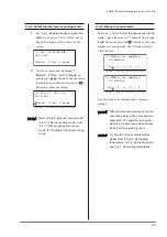
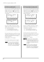
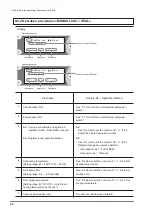
The vacuum level is determined by 

setting the vacuuming time.

 [

xx

]▼▲Dec/Inc      Move

      VAC TIME  

xx.x

sec

 HT 

xx

O

C x.

x

s CT 

xx

O

C

Operation number

Heat temp

Heat time

Cool temp

 [

xx

]▼▲Dec/Inc      Move

      VAC TIME  

xx.x

sec

 HT 

xx

O

F x.

x

s CT 

xx

O

F

Operation number

Heat temp

Heat time

Cool temp

The vacuum level is determined by 

setting the vacuuming time.

Display

1

2

3

5

4

6

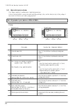
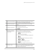
Circuit breaker ON.

Power button ON

3-a

  Call up a pre-installed or registered

operation mode:  “VAC+SEAL timer.”

Set heating temperature.
[Setting range: 60 ~ 250°C/ 140 ~ 480°F]

Set vacuum timer.
[Setting range: 0.1 ~ 99.9 seconds]

Set heating time.
[Setting range: 0.0 ~  2.0 seconds]

3-b

  Register a new operation pattern.

See “7-7 Turn ON the circuit breaker and power 

switch”.

See “7-7 Turn ON the circuit breaker and power 

switch”.

3-a

See “8-4 How to set the control unit” >>> “8-4-2

Select the desired operation number”.

See “8-4 How to set the control unit” >>> “8-4-5 Set 

heating temperature”.

See “8-4 How to set the control unit” >>> “8-4-11 

Vacuum gauge vacuuming mode”.

See “8-4 How to set the control unit” >>> “8-4-6 Set 

heating time”.

3-b

See “8-4 How to set the control unit” >>> “8-4-3

Register/change an operation pattern”.

Operation mode = “2 VAC+SEAL”
Vacuum mode = “2Time”

Procedure

Section No. / Operation Method

8-5-3 Operation procedures «TIMER VAC + SEAL»

Summary of Contents for V-460 Series

Page 1: ...Printed MAR 2017 2nd Edition 2 04E MICROCOMPUTER CONTROLLED TABLETOP NOZZLE TYPE B TYPE VACUUM SEALER V 460 610 SERIES OPERATING INSTRUCTIONS www vanderstahl com ...

Page 2: ...please set up the suitable operation patterns for your application Otherwise you cannot operate the machine in the way other than the pre installed operation patterns You can set the operation patterns according to the on screen display of the control unit Please refer to this manual for the detail 2 Seal test and optimum seal condition There are many variations of package materials and contents t...

Page 3: ...sed in this manual to easily identify the conditions of risks damages or some tips for the optimal use of your unit Caution Minor injuries or damages to the unit may occur when the instruction is ignored Warning Severe injuries or fatal accidents may occur when the instruction is ignored Danger Critical injuries or fatal accidents will almost certainly occur when the instruction is ignored Attenti...

Page 4: ...breaker and power switch 21 7 12 Inspection after operation 21 8 Control unit setting and operating procedures 22 8 1 Operate the machine with pre installed operation patterns 23 8 1 1 Sample operating procedures seal only operation 24 8 1 2 Sample operating procedures manual vacuum sealing operation 25 8 2 Register sample operation patterns 27 8 2 1 Sample case register a seal only operation mode...

Page 5: ...Sarcon sheet on the lower lever for all models 53 9 5 Replacing the silicone rubber and 38mm width glass tape for single side heating type 54 9 6 Replacing the silicone rubber for double side heating type 55 9 7 Connect and remove tube 55 9 8 Replacing the vacuum nozzle 56 9 9 Replacing the temperature sensor 57 10 Specification 58 Safety measures 60 Appearance dimensions drawing 62 11 Maintenance...

Page 6: ...lowing after opening the package Is the machine model the same as you have ordered Has any damage occurred during shipment Please make sure that all of the items described below are included in the package 1 Package contents Phillips screwdriver 1 pc Glass tape S W38mm x 5m roll D W25mm x 5m roll 1 each I heating element The accessories set will vary with according to the machine type Please refer...

Page 7: ...bels not readily apparent are indicated by dotted lines Explanation of the warning icons W1263 Caution electrical shock hazard do not touch W1264 Caution HOT do not touch during operation W1266 Caution crush hazard keep hands clear W1265 Caution rotating parts keep hands clear 2 Warning caution label location and content If warning caution labels peel off or are lost please purchase the proper lab...

Page 8: ...nplug this device before opening this cover W1173 W1265 W1264 W1266 WARNING Electrical Shock or Burn Hazard High Voltage Unplug this device before opening this cover W1173 Body cover and pressure lever Machine right side Warning Caution label location and content Cont d If Warning Caution labels peel off or are lost please purchase the proper labels and place them in the appropriate location ...

Page 9: ...firm proper electric power source Insert the electric power plug fully into the wall outlet Make sure power source has the specified voltage and electric power as explained in 10 Specification DO NOT use an extension cord as the machine may malfunction or may result in fire Machine will malfunction if connected to anything other than the specified voltage Warning Do not insert any metal objects in...

Page 10: ...cified When replacing parts always use only specified parts sold through Van der Stahl Scientific Not responsible for malfunctions caused by the use of unspecified parts Warning If the circuit breaker automatically turns to the OFF position If the circuit breaker automatically turns to the OFF position there is a possibility of machine malfunction such as short circuit Do not operate the machine u...

Page 11: ...l not to pinch your fingers to the sealing area When two or more operators are involved in the machine operation please pay extra attention to avoid accidents Caution Use machine properly Read the operating instructions carefully and operate sealer correctly Accidents or damage caused by misuse of the machine not in accordance with the operating instructions are the sole responsibility of the cust...

Page 12: ... tape silicone rubber becomes damaged The center dry tape silicone rubber will start to wear with use Once they are damaged it will be difficult to achieve smooth and strong seals Thoroughly read how to replace the parts and be careful when doing so Dust in the sealing area Dust will prevent attainment of a smooth seal It could also cause damage to heating element and or other routine maintenance ...

Page 13: ...torage but this will not have an effect on its use 4 The connecting ends of the I heating element may tarnish or show discoloration depending on the environment but this will not have an effect on its use When you order the spare heating element please make sure to order the I heating element referring to the parts numbers listed in 15 Consumable parts list Sticker The sticker of I heating element...

Page 14: ...Heating method Heater width LOP WKLFNQHVV WRWDO WKLFNQHVV RI SLOHG OP Single side heating 5mm 10mm Less than 0 3mm Double side heating 5mm 10mm Less than 0 4mm The V 460 610 is a tabletop impulse sealer equipped with a nozzle for removing air When the nozzle is inserted into a bag the bag will be securely locked by sponge rubber strips covering the sealing jaws and the air in the bag will be remov...

Page 15: ...o adjust its height and angle Air filter Store any objects taken in though the nozzle such as liquid and powder inside this air filter Air pedal Depress an air pedal to operate the machine Circuit breaker with overheat proof circuit The circuit breaker automatically switches off when the overheating or short circuit occurs Emergency stop switch Vacuum gauge Refer to a vacuum gauge manual included ...

Page 16: ...setting If you hold the or button in the numeric value will increase or decrease continuously Use this method when making wide range changes in setting Display screen Each setting is displayed on this screen Vacuum lamp The vacuum lamp turns ON during vacuuming process Heating lamp The heating lamp turns ON during heating process Cooling lamp The cooling lamp turns ON during cooling process Contro...

Page 17: ...o NOT use the sealer on a wet floor Do not expose the sealer to water drops or vapor This may cause a failure and or a short circuit of the machine Warning Do NOT carry the sealer by holding the lever arm nor pressure lever It can cause malfunction of the machine Use the handles on both sides of the machine Warning The power consumption varies depending on each model Check that the capacity of the...

Page 18: ...pins of the table legs on both sides of the table to the holes of angle steels By changing the level of holes you can adjust the table angle 2 Removing the drop pins is the reverse of the installation procedure Remove the drop pins from the holes while pushing them inside 7 3 Set an air pedal 7 4 Attach remove the table and how to adjust its height and angle Angle steel with holes Push inside Heig...

Page 19: ...located on the right side of the nozzle holder when facing toward it Turn the hollow screw using a hexagonal wrench Turning it clockwise change the nozzle tip angle downward Turning it counterclockwise change the nozzle tip angle upward After adjustment close the frame cover and fix it using screws 7 5 Nozzle position adjustment Remove screws Nozzle tip angle upward Nozzle tip angle downward Hexag...

Page 20: ...unctioning properly 7 7 Turn ON the circuit breaker and power switch 7 6 Test emergency stop system 1 Turn ON the circuit breaker 2 Turn ON the power switch Circuit breaker ON Press the emergency stop switch Test button ON OFF Turn to reset the E stop switch Attention The emergency stop switch remains to be activated unless it is reset by manually turning it clockwise Make sure to reset the emerge...

Page 21: ...r returns to the initial position and the sealing is complete If a sealing is not clean enough adjust the heating time or heating cooling temperature Also adjust the vacuuming if necessary 1 After finishing operation always turn OFF the power switch A cooling fan will stop running 2 Shut off the circuit breaker The machine will stop completely After use please clean up the parts Please refer to 9 ...

Page 22: ...explains how to register a new operation patterns with 2 examples Please try register a new operation pattern after reading this chapter 8 3 Explanation of the terms This chapter explains the commonly used terms on the display or in this manual Please refer to the Explanation of terms if you are not sure about the particular terms such as manual operation or impulse sealer 8 4 How to set the contr...

Page 23: ...8 5 1 Operation procedures SEAL ONLY Operation No 02 VAC SEAL manual The seal parameters set at the time of factory shipment HT Heating Temperature 140ºC 280ºF CT Cooling Temperature 100ºC 200ºF Refer to 8 5 Operation procedures 8 5 2 Operation procedures MANUAL VAC SEAL By pushing the buttons when the following is shown on the screen you can choose the desired operation number displayed on the sc...

Page 24: ... Sealing is complete Please make sure that the seal is properly performed When not using the machine for a while please make sure the followings a Turn OFF the power switch b Turn OFF the circuit breaker c Unplug the power outlet The pressure lever descends completely Sealing starts Heating lamp turns on 6 Depress an air pedal Pressure lever descends and the silicone sponges clamp the bag Please k...

Page 25: ...pedal 2nd Pressure lever descends and the silicone sponges clamp the bag Please keep on depressing the foot switch until the lever closes 7 Place a bag to the sealing area Set a pouch to the sealing area while confirming the seal position 10 When preferred vacuum is achieved depress an air pedal 4th again When an air pedal is depressed for the fourth time the following operating procedures will be...

Page 26: ... turns off The sealing is complete and the pressure lever returns to the initial position lever opens 11 Finish operation Sealing is complete Please make sure that the seal is properly performed When not using the machine for a while please make sure the followings a Turn OFF the power switch b Turn OFF the circuit breaker c Unplug the power outlet The pressure lever descends completely Sealing st...

Page 27: ... number 06 timer vacuuming seal Heating temperature 140ºC 280ºF Heating time 0 3 seconds Cooling temperature 100ºC 200ºF Vacuum time 12 0 sec 8 2 Register sample operation patterns Attention Maximum 10 operation patterns can be stored in the control unit If you are going to register over 10 operation patterns the message ALL 10 OPERATION PATTERNS ARE ENTERED DELETE ONE FOR A NEW ENTRY is displayed...

Page 28: ...n the screen 7 Move the cursor to 1 SEAL using the buttons 8 Press the button to select The following display will be shown on the screen 9 Set heating temperature to 140ºC 280ºF See 8 4 5 Set heating temperature for how to set the desired heating temperature 10 Move the cursor using button and set heating time to 0 3 seconds See 8 4 6 Set heating time for how to set the desired heating time 11 Mo...

Page 29: ...e buttons 8 Press the button to select The following display will be shown on the screen 10 Press the button to select The following display will be shown on the screen 11 Set vacuum time to 12 0 seconds See 8 4 10 Timer vacuuming mode for how to set the desired heating temperature 12 Set heating temperature to 140ºC 280ºF See 8 4 5 Set heating temperature for how to set the desired heating temper...

Page 30: ...from the fact that the current and heat are delivered on impulse or instantaneously Temperature sensor A temperature sensor is installed under the heating element directly measuring heat temperature Lever sponge position This is the lever position of when the machine is in the vacuuming mode The sponge rubbers clamp a pouch while vacuuming Lever upper position This is the lever position of when th...

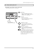
Page 31: ...uttons Press to show different setting mode Press to increase or decrease numerical setting value RIGHT LEFT arrow buttons Press to show different setting mode Press to move the cursor to the desired position Digital display See 8 5 Operation procedures for more detail 8 4 How to set the control unit Warning 1 If the operation is suspended when the lever is in sponge position the lever goes comple...

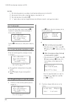
Page 32: ...it Push the button once to reduce the counter by one 8 4 1 Seal counter 8 4 2 Select the desired operation number When the entered operation is displayed on the control unit Ŷ 3UHVV button to display the next operation number Ŷ 3UHVV to display the previous operation number 8 4 3 Register change an operation pattern 1 When one of the entered operation modes is displayed 3 The below display will be...

Page 33: ...refer to 8 4 8 Select the desired vacuuming mode and set vacuuming mode accordingly 6 See 8 4 5 Set heating temperature and set heating temperature 7 See 8 4 6 Set heating time and set heating time 8 See 8 4 7 Set cooling temperature and set cooling temperature 9 After inputting cooling temperature press button Now the new operation pattern is successfully stored and the operation pattern just reg...

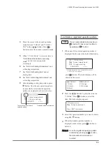
Page 34: ...ease or decrease continuously Use this method when making wide range changes in setting 6HWWLQJ UDQJH a Û 6HWWLQJ UDQJH a Û E g Before deletion No 1 SEALING ONLY No 2 VAC SEAL timer No 3 VAC SEAL manual After deleting 01 Seal only operation No 1 VAC SEAL timer No 2 VAC SEAL manual No 3 N A How to change heating temperature of the operation pattern NOT currently displayed Refer to 8 4 2 Select the ...

Page 35: ...d number press the button and go to procedure 2 The value will increase or decrease in 0 1 seconds increment by pressing the button once If you hold the button in the numeric value will increase or decrease continuously Setting range 0 0 2 0 second Go to procedure 2 2 The cursor will blink at the first digit of HT Press to move the cursor to the position of heating time x xs Adjust the heating tim...

Page 36: ...ed Refer to 8 4 2 Select the desired operation number After selecting the desired number press the button and go to procedure 2 2 The cursor will blink at the first digit of HT Press to move the cursor to the first digit of cooling temperature When the cursor is at this position adjust the cooling temperature by pressing Ɣ 8S EXWWRQ to increase the value Ɣ RZQ EXWWRQ to decrease the value 7KH YDOX...

Page 37: ...button When the cursor is placed at the desired mode press an button to confirm the setting 8 4 9 Manual vacuum mode Referring to 8 4 8 Select the desired vacuuming mode place the cursor to 1 Manual by pressing the button and press the button to select the manual vacuuming mode The following display will be shown Now the manual vacuuming mode is properly selected Attention Refer to 8 4 9 Manual va...

Page 38: ...ect the desired vacuuming mode place the cursor to 2 Time by pressing the button and press the button to select the timer vacuuming mode The following display will be shown The cursor will blink at the first digit of 1VG When the cursor is at this position adjust the vacuum degree by pressing Ɣ 8S EXWWRQ to increase the value Ɣ RZQ EXWWRQ to decrease the value The value will increase or decrease i...

Page 39: ...0mm 04 40mm 05 50mm 06 60mm 07 70mm 08 80mm Nozzle stroke accuracy is 2 to 3mm 1 Press the button and show the following display on the screen 2 Using the buttons place the cursor on 4 NZstroke 3 Press the button The following display will be shown on the screen 4 Using the button set the desired nozzle stroke Setting range is from 01 to 08 8 4 13 Maintenance mode 8 4 12 Setting nozzle stroke 1 Wh...

Page 40: ...PLQJ WKH VHDO position 3 b See 8 4 How to set the control unit 8 4 3 Register change an operation pattern Operation mode 1 SEAL Section No Operation Method 1 2 3 4 5 6 7 Circuit breaker ON Power button ON 3 a Call up a pre installed or registered operation mode SEAL ONLY Set heating temperature Setting range 60 250 C 140 480 F Set heating time Setting range 0 0 2 0 seconds Set cooling temperature ...

Page 41: ...sealing starts 2 Heating lamp turns ON 4 Cooling is finished Cooling lamp turns OFF 5 Sealing process is complete 3 After the heating is finished heating lamp is turned OFF cooling lamp turns ON Refer to 7 10 Turn OFF the circuit breaker and power switch to turn OFF the machine When not using the machine for a while unplug the machine from the outlet ...

Page 42: ...ting range 40 C 100 F Up to the set heating temperature by the user Depress an air pedal 1st 3 b Register a new operation pattern Procedure See 7 7 Turn ON the circuit breaker and power switch See 7 7 Turn ON the circuit breaker and power switch 3 a See 8 4 How to set the control unit 8 4 2 Select the desired operation number See 8 4 How to set the control unit 8 4 5 Set heating temperature See 8 ...

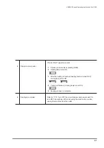
Page 43: ...t d When you depress the foot switch for the forth time the following procedures from 1 to 6 are performed automatically 1 Vacuuming finishes and the vacuum lamp turns OFF 2 Nozzle returns to the back position 3 Pressure lever closes and sealing starts Heating lamp turns ON Vacuuming starts Vacuum lamp turns ON 5 Cooling is finished Cooling lamp turns OFF 6 Sealing process is complete The pressure...

Page 44: ...ange 60 250 C 140 480 F Set vacuum timer Setting range 0 1 99 9 seconds Set heating time Setting range 0 0 2 0 seconds 3 b Register a new operation pattern See 7 7 Turn ON the circuit breaker and power switch See 7 7 Turn ON the circuit breaker and power switch 3 a See 8 4 How to set the control unit 8 4 2 Select the desired operation number See 8 4 How to set the control unit 8 4 5 Set heating te...

Page 45: ...press the foot switch for the forth time the following procedures from 1 to 7 are performed automatically 1 Vacuuming starts Vacuum lamp turns ON 2 When the set up time is passed vacuum is finished Vacuum lamp turns OFF 3 Nozzle returns to the back position 4 Pressure lever closes and sealing starts Heating lamp turns ON 6 Cooling is finished Cooling lamp turns OFF 7 Sealing process is complete Th...

Page 46: ...tered operation mode VAC SEAL gauge Set heating temperature Setting range 60 250 C 140 480 F Set vacuum level Setting range 1 100kPa Set heating time Setting range 0 0 2 0 seconds 3 b Register a new operation pattern See 7 7 Turn ON the circuit breaker and power switch See 7 7 Turn ON the circuit breaker and power switch 3 a See 8 4 How to set the control unit 8 4 2 Select the desired operation nu...

Page 47: ... foot switch for the forth time the following procedures from 1 to 7 are performed automatically 1 Vacuuming starts Vacuum lamp turns ON 2 When the vacuum degree reaches to the set up value vacuum process finishes Vacuum lamp turns OFF 3 Nozzle returns to the back position 4 Pressure lever closes and sealing starts Heating lamp turns ON 6 Cooling is finished Cooling lamp turns OFF 7 Sealing proces...

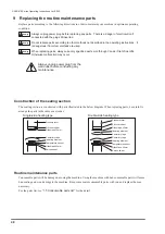
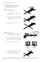
Page 48: ...the routine maintenance parts Construction of the sealing section Routine maintenance parts Pressure lever Silicone rubber Center dry tape I heating element Glass tape 25mm Sarcon sheet Glass tape 38mm Temperature sensor Pressure lever Silicone rubber Glass tape 25mm I heating element I heating element Glass tape 25mm Sarcon sheet Center dry tape Center dry tape Temperature sensor Warning Warning ...

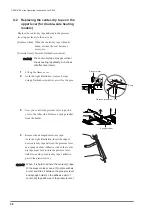
Page 49: ...ht 5 Fold the center dry tape along edges so that the other side of the tape adheres to the other side of the seal receiving plate 6 Attach the sponge holder and fix it with the white plastic nuts Replace the center dry tape adhered to the seal receiving plate lower lever to the new one 9 1 Replacing the center dry tape on the lower lever for all models Sponge holder 樹脂ナッ ト Plastic nut Seal receiv...

Page 50: ...n the right illustration insert the edge of new center dry tape between the pressure lever and sponge holder Adhesive side of the center dry tape must face toward the pressure lever Adhere one side of center dry tape s adhesive part to the pressure lever 9 2 Replacing the center dry tape on the upper lever for double side heating models Pressure lever Sponge rubber E ring Pin Flathead screwdriver ...

Page 51: ...he left and right 6 Fold the center dry tape along edges so that the excess tape over the seal receiving plate adheres to the other side of the plate Pressure lever Sponge holder Attention Apply the tape so that the nonadhesive central part of the tape covers the heating element Make sure there is no wrinkles on the tape Wrinkles will negatively affect the sealing surface ...

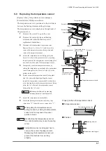
Page 52: ... the screws return the electrode lever to the initial position 6 Attach the electrode covers 9 3 Replacing I heating element Turn Lift up Insert the heating element terminal here Heating element Heating element securing screw Electrode cover Electrode cover securing screw Electrode lever Warning Warning Do NOT replace a fusing heating element to the ones with different width Warning Warning For yo...

Page 53: ...5mm 5 Fold the glass tape along both edges so that the excess tape over the lever adheres to the sides of the clamping lever The glass tape and Sarcon Sheet are sold individually 9 4 Replacing 25mm width glass tape and Sarcon sheet on the lower lever for all models Electrode Adhere the glass tape over the Sarcon Sheet Fold along both edges and adhere to the sides of the clamping lever Glass tape A...

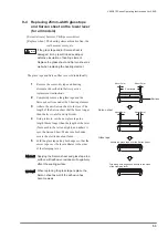
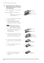
Page 54: ...length of pressure lever at both ends Adhere it over the silicone rubber 5 Fold up the excess portion of glass tape at both ends of the pressure lever and adhere to the end faces 6 As in the right illustration fold the glass tape again along the side edges 7 Fold up the excess part of the tape along the sides of pressure lever as in the right illustration 9 5 Replacing the silicone rubber and 38mm...

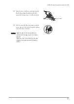
Page 55: ...ed in their respective replacement instructions 2 Remove the damaged silicone rubber Using an industrial purpose alcohol etc completely remove the adhesive residues remaining on the metal portion of the pressure lever 3 Remove the paper liner from the new silicone rubber and adhere it to the lever starting from the edge 9 7 Connect and remove tube 9 6 Replacing the silicone rubber for double side ...

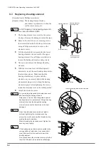
Page 56: ...le make sure that the nozzle holder is in fully back position 2 Insert the nozzle into the nozzle holder Adjust the nozzle position so its tip vacuum side is about 8mm away from the seal receiving plate 3 Also adjust the leveling of vacuum nozzle 4 Tighten the cap bolt using a hexagonal wrench to securely fix the vacuum nozzle 5 Install the L type elbow to the nozzle end 9 8 Replacing the vacuum n...

Page 57: ...See the picture on the right 6 Firmly secure the temperature sensor fixing plate the A 2 side while lightly pulling the sensor toward the temperature sensor module so that there is no slacking between the temperature sensor fixing plate the A 1 side and the temperature sensor fixing plate the A 2 side 7 Secure the temperature sensor module 8 Attach the heating element and center dry tape removed i...

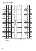
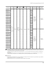
Page 58: ...0 C H 10D 220V 3 0kW 10mm V 610 C 5 110V 220V 1 5kW 50RNS 39L min 87 0kPa Single side heating 610mm 5mm V 610 C 10 2 8kW 10mm V 610 C 5D 1 5kW Double side heating 5mm V 610 C 10D 220V 2 8kW 10mm V 610 C S 5 110V 220V 1 5kW FDP 10 10L min x 2 58 6kPa Single side heating 610mm 5mm V 610 C S 10 2 8kW 10mm V 610 C S 5D 1 5kW Double side heating 5mm V 610 C S 10D 220V 2 8kW 10mm V 610 C H 5 110V 220V 1...

Page 59: ...0 C H 5D 60k g V 610 C H 10D 65k g Structurally the nozzle vacuum system will cause attainable vacuum level to be erratic when operating the machine in low vacuum of between 1 to 20 kPa Additional discussion is necessary for low vacuum operation The button on the control unit allows you to set the vacuum level from 1 to 100 kPa but the actual vacuum level will depend on the ability of the pump mou...

Page 60: ... sealing area KHQ WKH OHYHU LV EHLQJ SUHVVHG GRZQ LI D IRUHLJQ REMHFW VXFK DV D QJHU LV FDXJKW LQ WKH VHDOLQJ DUHD DQG SUHYHQWV WKH OHYHU IURP FRPSOHWLQJ LWV PRWLRQ ZLWKLQ D VSHFL HG SHULRG RI WLPH WKH OHYHU will be released and will return to its initial position Heating element malfunction prevention 7R SUHYHQW KHDWLQJ ZKLOH WKH OHYHU LV LQ WKH RSHQ SRVLWLRQ SRZHU GRHV QRW ÀRZ WR WKH KHDWLQJ ele...

Page 61: ...V 460 610 Series Operating Instructions Ver 2 04E 61 ...

Page 62: ...60 610 Series Operating Instructions Ver 2 04E 62 415 280 Seal position 435 350 785 570 470 415 280 Seal position 435 350 785 620 676 Appearance dimensions drawing V 460 series V 610 series Unit mm Unit mm ...

Page 63: ...ions Ver 2 04E 63 415 280 Seal position 435 350 785 570 470 100 Duct bracket for centralized exhaust 80 115 415 280 Seal position 435 350 785 620 100 Duct bracket for centralized exhaust 80 115 V 460C series V 610C series Unit mm Unit mm ...

Page 64: ...Ensure that there is no foreign objects being stuck to the piping and or elbows Annual maintenance Silicone rubber Ensure that there is no damage burning or crack If yes replace the silicone rubber Temperature sensor 2 Ensure that there is no damage or tarnishing of the temperature sensor Maintenance in every three years Overhaul the machine and replace the below listed parts if any abnormality oc...

Page 65: ...flector with your hand and rotate the baffle clockwise to remove it from the deflector Now the filter element is detached Attaching the filter cup and filter element 4 Attach the filter element to the deflector and set the baffle in the position Rotate the baffle counterclockwise to fix it 5 Insert the filter element assembly into the filter cup Rotate the deflector to either right or left 45 degr...

Page 66: ...V 460 610 Series Operating Instructions Ver 2 04E 66 12 Electric diagram 110V ...

Page 67: ...V 460 610 Series Operating Instructions Ver 2 04E 67 220V ...

Page 68: ...V 460 610 Series Operating Instructions Ver 2 04E 68 13 Piping diagram V 460 610 series ...

Page 69: ...V 460 610 Series Operating Instructions Ver 2 04E 69 V 460 610C series ...

Page 70: ... temperature too high OORZ VXI FLHQW FRROLQJ E ORZHULQJ the set cooling temperature Is the glass tape or Sarcon sheet damaged Replace the glass tape or Sarcon sheet Is the electrode damaged Replace the electrode VHDO V QLVKHG FRQGLWLRQ GLIIHUV RQ the right side and left side Only one side fuses etc Is only one side of the silicone rubber worn or dented Replace the silicone rubber Heating element i...

Page 71: ...nit may be damaged and replacement is required Release the pressure lever by pressing the ENT button Be careful of the pressure lever as it goes completely down before released Problems Check Solution The circuit breaker trips Does the circuit breaker trip while heating Check if the correct voltage is provided to the power source side Control unit may be damaged Replace the control unit Does the c...

Page 72: ... required Lever upper position error Lever sponge position error Lever lower position error Nozzle back position error Nozzle front position error NG X1 SENSOR PROBLEM Press ENT to escape NG X1 LEVER UPPER Press ENT to escape NG X4 NOZZLE BACK Press ENT to escape NG X2 LEVER SPONGE Press ENT to escape NG X3 LEVER LOWER Press ENT to escape NG X5 NOZZLE FRONT Press ENT to escape 14 2 Error display 2...

Page 73: ...be damaged Contact your local dealer or FUJIIMPULE HEATING FAULT Press ENT to escape This error is displayed when the machine does not reach to the set heating temperature within the Is the temperature sensor properly installed The machine cannot measure temperature if the temperature sensor is not installed properly See 9 9 Replacing the temperature sensor and install it properly ĺ R RX XVH DQ H ...

Page 74: ...Silicone rubber 610 2 pcs set 49900 Sponge rubber 460 2 pcs set 49951 Sponge rubber 610 2 pcs set 18115 Plastic nut white 5mm 5 pcs set 39434 Glass tape 25 mm x 5m 1 roll 39435 Glass tape 25 mm x 10m 1 roll 877020 Glass tape 38 mm x 5m 1 roll 39432 Glass tape 38 mm x 10m 1 roll 39441 Center dry tape 40mm x 5m 1 roll 49902 Sarcon sheet 460 2 pcs set 49952 Sarcon sheet 610 2 pcs set 39630 Sarcon she...

Page 75: ...V 460 610 Series Operating Instructions Ver 2 04E 75 ...

Page 76: ...Y7019 MAR 2017 2nd Edition V 460 610 Series Operating Instructions Ver 2 04E Represented by 1652 Plum Lane Redlands CA 92374 800 550 3854 www vanderstahl com ...

Reviews: