background image

14

The eyepieces and objectives on VanGuard Microscopes are coated.  They should 

never be wiped while dry as any dirt or dust will scratch the coating.  The surfaces 

should either be blown off with an air canister, or blown and cleaned with an air-bulb and 

camel-hair brush.  It is recommended to then use a lens cleaner.  Apply with a cotton 

swab for a minimum of wetting, then wipe the surface clean with a quality lens tissue.  

Xylene, since it breaks down the bonding material holding the lenses, should never be 

used as a cleaner.  Periodically your VanGuard Microscope should be fully serviced by 

a qualified service technician.  

Maintenance

If the microscope is plugged in but the lamp is not turning on, the fuses could be blown.  

To check the fuses, UNPLUG THE MICROSCOPE FROM YOUR POWER SOURCE 

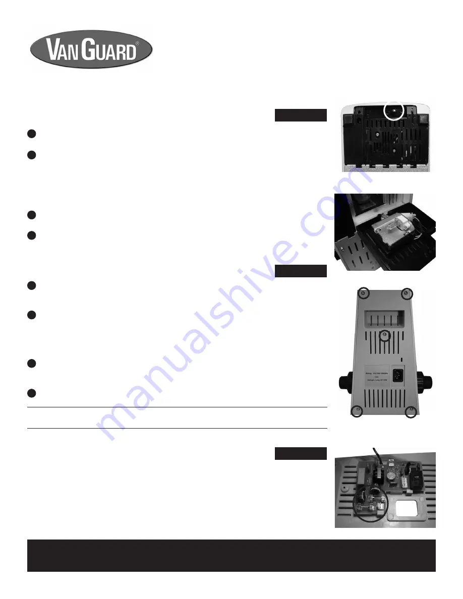
and remove the 5 screws securing the back panel (see figure 17).

Once the screws are removed, carefully pull the rear cover away from the microscope.  

There is a small circuit board connected to the rear cover that houses the two fuses (see 

figure 18 - note: connecting wires removed for clarity).  Avoid pulling on the rear cover 

hard enough to loosen any of the wires that connect the circuit board to the microscope.  
To replace the blown fuse(s) (the wire inside is broken, or the glass is blackened) pull 

the fuse out of it’s holder and snap a new fuse in.  You might need to use a screwdriver 

to lever the fuse out, but be careful not to scratch the circuit board.

Replace the rear cover and the five screws.

Replacing the Fuse

1

2

3

4

Before attempting to replace or remove the lamp, UNPLUG THE MICROSCOPE FROM 

ANY POWER SOURCE AND ALLOW SUFFICIENT TIME FOR THE LAMP TO COOL.  

Lamp replacement is done by laying the microscope on its back and opening the trap 

door located on the bottom of the base by pulling on the release knob (see figure 15).

Note: Be careful not to touch the glass lamp when replacing -- use a tissue or 

other medium to grasp the lamp.  This will prevent the oils from your hand from 

reducing lamp life.  If contact is made with the lamp, clean lamp with rubbing 

alcohol and allow a brief drying period.

Once the door is open, the lamp can easily be removed simply by grasping the lamp 

and pulling it from the fixture (see figure 16).
When replacing, insert the new lamp into the same fixture.  Make sure that the pins on 

the lamp slide easily into the slots.  You should not have to force the lamp.  

Replacing the Lamp

1

2

3

4

Figure 17

Figure 18

Figure 16

Figure 15

Maintenance

Replacement Lamp

 -- 20W Halogen (Part No. 1400-20WHL)

Replacement Fuse

 -- 0.25A, 250V (Part No. 1400-FS1) [2 required]

All Models

All Models

All Models

For information about parts, accessories, or service -- contact your dealer directly or contact 

VanGuard Microscopes at 1-800-423-8842.

Summary of Contents for 1400 Series

Page 1: ...Covering Models 1420BR 1421BR 1430BR 1431BR 1423PH 1433PH Operation Manual 1400 Series...

Page 2: ...ide holder and a chemical resistant finish Motion is controlled by a right hand low position coaxial control and is driven by a rack and pinion system Focusing Movement Coaxial ultra low position coar...

Page 3: ...el 1423PH Binocular Head 1 ea Stand 1 ea Phase Contrast Condenser 1 ea Phase Contrast Centering Telescope 1 ea 10X Eyepiece 2 ea 10X Plan Phase Objective 1 ea 20X Plan Phase Objective 1 ea 40X Plan Ph...

Page 4: ...art Numbers Scale Reticle Call for Part Numbers Stage Micrometer Call for Part Numbers 20X Eyepieces Call for Part Numbers Objectives Achromatic 4X 10X 20X 40X 60X 100X oil Plan Achromatic 4X 10X 20X...

Page 5: ...Port Mechanical Stage Head Assembly Focusing Tension Control Knob Prism Slider Camera Port Dust Cap Phase Annulus Turret Substage Adjustment Knob Diopter Adjustment Mechanism Interpupillary Adjustment...

Page 6: ...6 1400 Series Parts Power Cord Jack 1400 Series Rear View Carrying Handle Power Switch Variable Lighting Control Up Stop Mechanism 1400 Series Lower Left View Substage Adjustment Knob...

Page 7: ...set screw using the included hex wrench see figure 1 NOTE Do not release the head until it is firmly secured with the head set screw Assembly 1 2 3 4 5 Figure 2 Figure 3 7 All Models If you are setti...

Page 8: ...re 6 Make sure that the text NA 1 25 is facing up as you install the condenser If the condenser will not slide freely through the silver ring and you ve checked that the condenser set screw is backed...

Page 9: ...condenser assembly While looking into the microscope eyepieces close the field iris diaphragm to the smallest setting by turning the uppermost section of the substage illuminator counter clockwise Cl...

Page 10: ...contrast centering telescope should resemble rings superimposed on one another see Figure 7A What is actually being viewed are the phase rings Turn the condenser centering knobs which extend from the...

Page 11: ...stage X Y controls located underneath the right hand side of the stage see figure 9 provide easy and accurate positioning of the sample One complete turn of the longitudinal Y control lower half of th...

Page 12: ...t mechanism located on the right eyetube see figure 12 Once complete the microscope is corrected for your vision Interpupillary and Diopter Adjustments Figure 12 Figure 11 1 2 3 The 100X objective whi...

Page 13: ...vert the image to the camera port The prism slider is the silver knob on the right side of the head assembly see figure 13 Note The 1400 Series Microscopes utilize a 70 30 split sliding prism This spl...

Page 14: ...s is blackened pull the fuse out of it s holder and snap a new fuse in You might need to use a screwdriver to lever the fuse out but be careful not to scratch the circuit board Replace the rear cover...

Page 15: ...1 8mm F O V Plan Achromatic 20X 0 40 N A 0 50mm W D 0 9mm F O V 40X 0 65 N A 0 40mm W D 0 45mm F O V 100X 1 25 N A 0 25mm W D 0 18mm F O V Stage Dimensions 140mm x 140mm Stage Motion Right Hand Coaxia...

Page 16: ...ir or replacement of parts by the End User or an unauthorized third party while under warranty 4 Consumable items such as but not limited to bulbs have failed This warranty expressly excludes transpor...

Page 17: ...Printed in the USA No VGMNL081919 1400BR PH...

Reviews: