background image

Setup

Note:  This completes the setup for the 1486FLi.  The next 5 pages will explain how to use and make adjustments  

to the microscope.

12

1.

  Begin by turning on the 

substage illuminator

 with the 

power switch

 located on the 

lower left side of the instrument. Set the 

objectives

 so they are in the approximate 

position for actual use. This is best achieved by placing a slide on the 

stage

rotating the 100X 

objective

 into position, then raising the stage (via the 

coarse/

fine focus control

 knobs) until the tip of the 100X 

objective

 is just above the slide 

(almost touching).  

2.

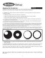
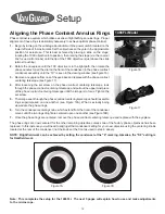
  Rotate the 

nosepiece

 until the 10X 

objective

 is in the light path, then rotate the 

phase annulus turret

 (the dial on the front of the condenser) in the 

phase contrast 

condenser assembly

 until the “10” is seen in the viewing window (see figure 16).  

3.

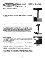
  Remove an 

eyepiece

 from one of the 

eyetubes

 and replace with the 

phase contrast 

centering telescope 

(see figure 17).  

4.

  After loosening the set screw on the 

phase contrast centering telescope

, look 

through the 

phase contrast centering telescope 

and


pull out the uppermost piece 

of the 

phase contrast centering telescope

 until the image is in focus. Tighten the 

set screw.

5.

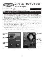
  The image seen through the 

phase contrast centering telescope

 should resemble 

rings superimposed on one another (see Figure 18A). What is actually being 

viewed are the phase rings.

6.

  Turn the 

condenser centering knobs

, which extend from the front of the condenser 

mount, until the two rings of light are centered upon one another (see Figure 18B).

Aligning the Phase Contrast Annulus Rings

Phase contrast is a system which utilizes a series of light baffling annulus rings.  Proper 

alignment of these rings is absolutely necessary to achieve optimal phase contrast.

Figure 7B

Figure 7A

1486FLi Model

Figure 17

Figure 16

7.

  Once the phase rings are centered, remove the 

phase contrast centering telescope

 and replace with the 

eyepiece

.

The phase rings are now centered for the other remaining 

objectives

 unless one of the factory phase objectives has been 

replaced. In this instance you will need to align just that condenser setting for your new objective using the centering knobs 

located at the rear of the condenser (not the knobs at the front as used in step 6 above).

NOTE:  Brightfield work can be achieved by setting the condenser at the “0” marking. Likewise, the “DF” setting is 

for Darkfield work.

Summary of Contents for 1400FLi Series

Page 1: ...Operation Manual 1400FLi Series Covering Models 1482FLi 1486FLi...

Page 2: ...adjustment and safety autostop Condenser Model 1482FLi comes with a 1 25 N A Abbe Condenser Model 1486FLi comes with a 1 25 N A Zernike condenser with phase annulus rings for 10X 20X 40X and 100X als...

Page 3: ...uction Manual 1 ea Model 1486FLi Trinocular Head 1 ea Stand 1 ea Phase Contrast Brightfield Darkfield Condenser 1 ea Phase Contrast Centering Telescope 1 ea Epi Illumination Assembly 1 ea External Pow...

Page 4: ...ra System 5 Megapixels 1400 CDPC 3 USB Color Digital Camera System 3 Megapixels Other Accessories Part Number Description Call for Part Numbers Scale Reticle Call for Part Numbers Stage Micrometer Cal...

Page 5: ...Diopter Adjustment Mechanism Interpupillary Adjustment Mechanism UV Shield Set Screw Mercury Lamp Centering Window Horizon tal Lamp Centering Knob Vertical Lamp Centering Knob Lamp Door Set Knob Epi I...

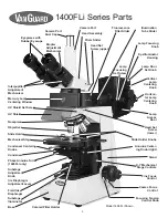
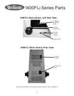
Page 6: ...rnal power supply are shown on page 16 Power Switch Variable Lighting Control Up Stop Mechanism 1400FLi Series Base Left Side View Substage Adjustment Knob Power Cord Jack 1400FLi Series Stand Rear Vi...

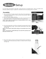
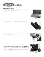
Page 7: ...bly on top of the epi illuminator housing assembly so that the dovetail flange slides into place Secure with the knurled head set screw upper see figure 2a NOTE Do not release the head until it is fir...

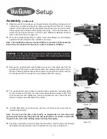
Page 8: ...holes of the nosepiece see figure 6 9 Raise the substage and stage to their maximum height Raise the stage via the coarse fine focus controls see figure 7a and the substage using the substage adjustm...

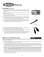
Page 9: ...bracket access door located on the right side of the housing Once loosened lift the access door up and away from the housing 14 The epi illuminator lamp bracket is shipped with a protective insulating...

Page 10: ...t of the Mercury Lamp NOTE Please see page 16 to familiarize yourself with the operation of the external power supply before turning the external power supply on 21 Plug the power supply cable see fig...

Page 11: ...kwise Closing the iris in this manner will reduce the field so that a small white hexagon is visible within a black field see figure 15A Focusing of the hexagon is performed by turning the substage ad...

Page 12: ...ce of the phase contrast centering telescope until the image is in focus Tighten the set screw 5 The image seen through the phase contrast centering telescope should resemble rings superimposed on one...

Page 13: ...intensity Focusing and Mechanical Stage Mechanisms The up stop mechanism is located just inside of the left hand focus control knob see figure 20c It allows the user to set a maximum point to which t...

Page 14: ...stment mechanism located on the right eyetube see figure 22a Once complete the microscope is corrected for your vision Interpupillary and Diopter Adjustments The 100X objective which comes with this m...

Page 15: ...Li is used mainly for adding contrast and photograph color correction during phase contrast work The blue filter is used to approximate natural light and photograph color correction Filtering is a use...

Page 16: ...replacement reset the timer by inserting a small pin paperclip etc into the reset hole located on the front of the power supply face 7 Although the lamp has a finite service life it is recommended th...

Page 17: ...ur 1400FLi Series Microscope 100W HBO Short Arc Mercury Lamps The supplied 100W HBO Short Arc Mercury Lamps have a discharge vessel made of high optical quality quartz glass containing mercury and a n...

Page 18: ...ut be careful not to scratch the circuit board 4 Replace the rear cover and the five screws Replacing the Microscope Fuse 1 Before attempting to replace or remove the lamp UNPLUG THE MICROSCOPE FROM A...

Page 19: ...0X 1 25 N A 0 25mm W D 0 18mm F O V Fluorescence Filter Cubes Blue Broadband Dichroic 500nm Excitation 430 490nm Emmision 520nm Intended Dyes FITC Acridine Orange Auramine Green Broadband Dichroic 570...

Page 20: ...ir or replacement of parts by the End User or an unauthorized third party while under warranty 4 Consumable items such as but not limited to bulbs have failed This warranty expressly excludes transpor...

Page 21: ...Printed in the USA VGMNL081319 1480FLi www veegee com 800 423 8842 sales veegee com techsupport veegee com veegee com pages technical support service...

Reviews: