5000/10000 FLYWHEEL GRINDER
GRINDING FLYWHEEL (continued)
4. This step is for machines equipped with auto grind only:
a. Determine depth of grind (amount of material to be removed).
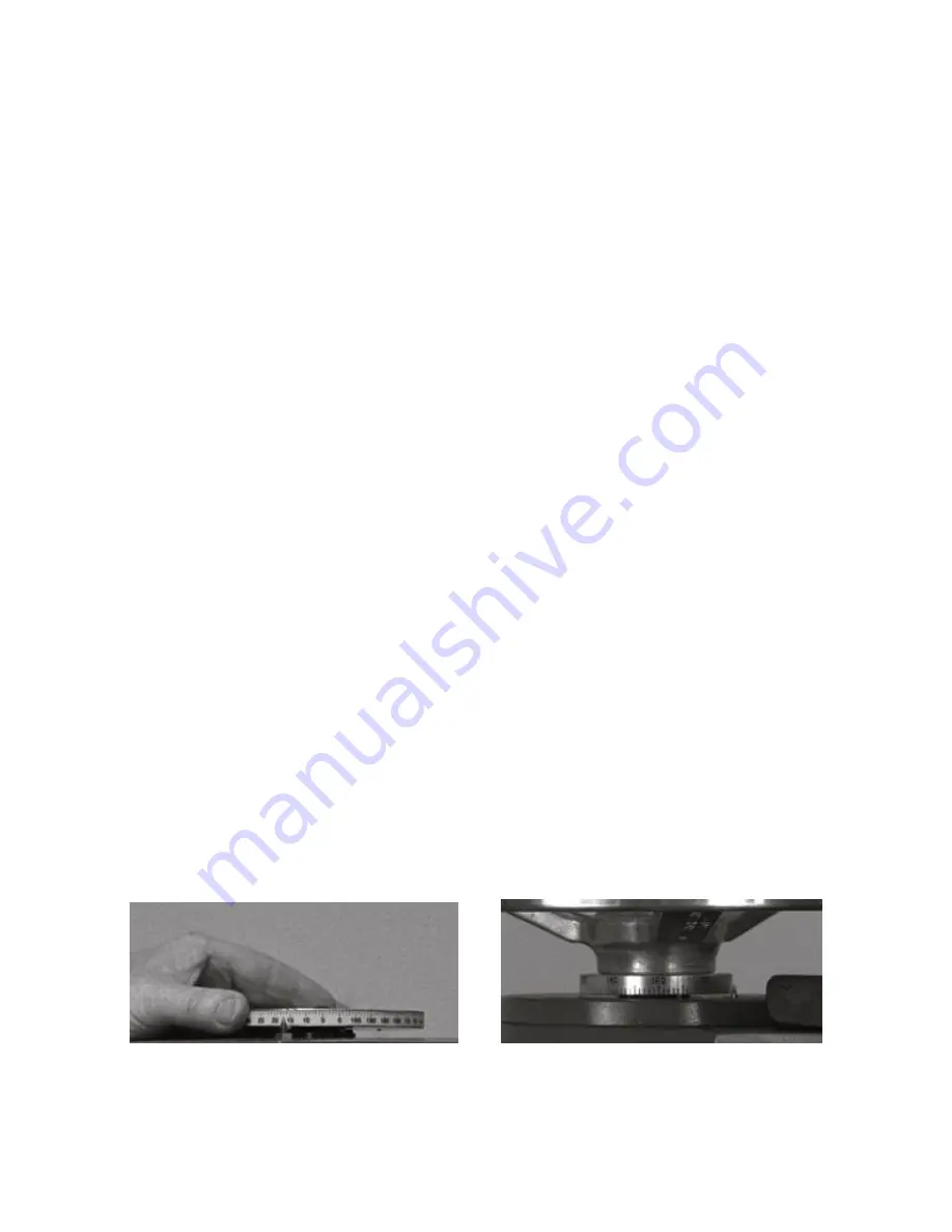
b. Rotate graduated dial to that amount lined up with pointer (Figure 24)
c. Select downfeed rate with variable feed rate dial.
d. Start auto grind by depressing “on” switch.
e. Auto grind will stop feeding and turn off when the preset depth is reached (feed may
temporarily stop as it senses the grinder motor being overloaded and then restart
automatically during the auto grind process until finished).
f. Turn off table, grinder head motor, and coolant after sparkout.
5.
SURFACE FINISH:
Keep the grinding wheel cutting at all times never allow the wheel to
coast for a long period of time without feeding it downward. long periods of coasting will
cause the grinding wheel to glaze and load up. The only exception to this is when it is
desired to obtain a very smooth finish. A wide variety of surface finishes are obtainable
using the grinder without varying the grit size of the grinding wheel. This range of surface
finish is obtained by varying the pressure exerted on the grinding wheel. A coarse finish is
obtained by feeding heavily then backing off the work piece quickly. Smoother finishes are
obtained by backing off the workpiece then coming back down with a very light feed
pressure.
6.
RECESSED FLYWHEELS:
When grinding recessed flywheels, the depth dimension from
the pressure plate mounting surface to the clutch friction surface should be restored after
grinding of the friction surface. This is done by grinding the pressure plate mounting surface
an amount equal to that ground off the friction surface. The steps followed in grinding
recessed flywheels are as follows:
a. Mount flywheel on machine.
b. If original equipment specs are unavailable, use a depth micrometer to measure depth
from pressure plate mounting surface to an unworn area of the clutch friction surface.
c. Grind friction surface to clean up.
d. Use depth micrometer again to measure new depth. Subtract original depth from this
measurement to obtain amount to be removed from pressure plate mounting surface.
e. Locate dial indicator on pressure plate mounting surface, set dial to zero.
f. Grind surface until dial indicator reading changes by the proper amount.
7. While a dial indicator or a depth micrometer is used to measure a specific amount of
material, the graduated dial (Figure 24 & 25) will give the operator an approximate amount
of material removal. The readings of this dial will be influenced by both stock removal and
wheel wear.
Figure 24
Figure 25
Van Norman
29.
888-855-1789
Summary of Contents for FG10000
Page 2: ......
Page 4: ......
Page 11: ...5000 10000 FLYWHEEL GRINDER STANDARD EQUIPMENT FG5000 FG10 000 Van Norman 7 888 855 1789...
Page 21: ...5000 10000 FLYWHEEL GRINDER MACHINE DESCRIPTION Van Norman 17 888 855 1789...
Page 41: ...5000 10000 FLYWHEEL GRINDER ASSEMBLY DRAWING Van Norman 37 888 855 1789...
Page 42: ...5000 10000 FLYWHEEL GRINDER ASSEMBLY DRAWING Van Norman 38 888 855 1789...
Page 43: ...5000 10000 FLYWHEEL GRINDER ASSEMBLY DRAWING Van Norman 39 888 855 1789...
Page 44: ...5000 10000 FLYWHEEL GRINDER ASSEMBLY DRAWING Van Norman 40 888 855 1789...
Page 81: ......


