5000/10000 FLYWHEEL GRINDER
MACHINE SET-UP (continued)
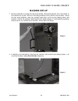
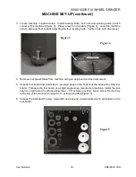
3. Locate machine in desired area. Install leveling bolts, lock nuts and leveling pads in each
corner of the machine (Figure 3). Place a level on the table (Figure 4). Level the machine
side-to-side and front to back adjusting the four leveling bolts. Tighten lock nuts when level.
Figure 3
Figure 3
Figure 4
4. Remove rust preventative from machine using an approved commercial solvent.
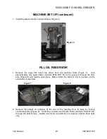
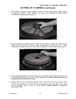
5. Unpack tool board and install the 2 - wooden pegs on the bottom of the back side of the tool
board. This sets the tool board at a slight angle when mounted on machine. Install the tool
board on right side of machine using the 2 - 1/4" screws provided. Next, screw the tool tray
to the top of the tool board using the 3 - screws provided (Figure 5).
6. Unpack the Standard Tooling, clean with an approved commercial solvent, and place on the
tool board.
Figure 5
Van Norman
19.
888-855-1789
Summary of Contents for FG5000
Page 2: ......
Page 4: ......
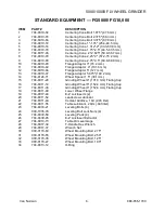
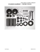
Page 11: ...5000 10000 FLYWHEEL GRINDER STANDARD EQUIPMENT FG5000 FG10 000 Van Norman 7 888 855 1789...
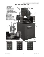
Page 21: ...5000 10000 FLYWHEEL GRINDER MACHINE DESCRIPTION Van Norman 17 888 855 1789...
Page 41: ...5000 10000 FLYWHEEL GRINDER ASSEMBLY DRAWING Van Norman 37 888 855 1789...
Page 42: ...5000 10000 FLYWHEEL GRINDER ASSEMBLY DRAWING Van Norman 38 888 855 1789...
Page 43: ...5000 10000 FLYWHEEL GRINDER ASSEMBLY DRAWING Van Norman 39 888 855 1789...
Page 44: ...5000 10000 FLYWHEEL GRINDER ASSEMBLY DRAWING Van Norman 40 888 855 1789...
Page 81: ......

