5000/10000 FLYWHEEL GRINDER
SETTING UP FLYWHEEL (continued)
3. Clean table and lay proper flange adapter on table. Use the largest possible flange adapter
for maximum support. Place flywheel onto table with crankshaft mounting surface
contacting the flange adapter (Figure 20).
4. Choose proper size centering cone to fit center hole in flywheel. (Figure 21) Select correct
length centering cone bolt. Secure to table by tightening centering cone bolt. If exact
centering is necessary such as on some recessed flywheels, a dial indicator may be used.
5. Position grinding wheel over friction surface to be ground and lock grinding head in place by
pulling headlock handle on left side of head downward. POSITION WHEELGUARD FOR
MAXIMUM OPERATOR PROTECTION.
6. Replace shroud cover and actuate grinder motor, table motor and coolant pump. Direct
coolant onto workpiece so it flows under the grinding wheel. Regulate amount of coolant
flow by adjusting valve on rear of shroud. NEVER GRIND WITHOUT ADEQUATE
COOLANT FLOW.
Van Norman
27.
888-855-1789
Summary of Contents for FG5000
Page 2: ......
Page 4: ......
Page 11: ...5000 10000 FLYWHEEL GRINDER STANDARD EQUIPMENT FG5000 FG10 000 Van Norman 7 888 855 1789...
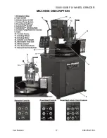
Page 21: ...5000 10000 FLYWHEEL GRINDER MACHINE DESCRIPTION Van Norman 17 888 855 1789...
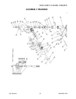
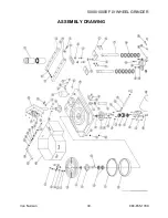
Page 41: ...5000 10000 FLYWHEEL GRINDER ASSEMBLY DRAWING Van Norman 37 888 855 1789...
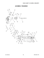
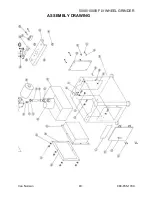
Page 42: ...5000 10000 FLYWHEEL GRINDER ASSEMBLY DRAWING Van Norman 38 888 855 1789...
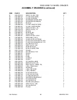
Page 43: ...5000 10000 FLYWHEEL GRINDER ASSEMBLY DRAWING Van Norman 39 888 855 1789...
Page 44: ...5000 10000 FLYWHEEL GRINDER ASSEMBLY DRAWING Van Norman 40 888 855 1789...
Page 81: ......

