SECTION 5: MAINTENANCE
AIR N ARC
®
150 SERIES
PAGE - 36
090051-OP_r0 (FEB-2014)
Vanair Manufacturing, Inc.
vanair.com • 800-526-8817
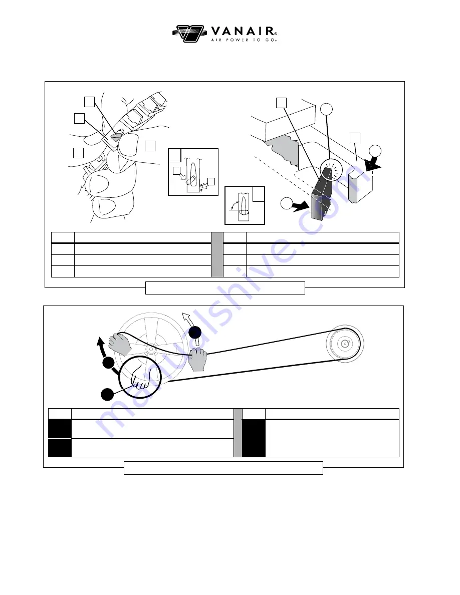
KEY
DESCRIPTION
KEY
DESCRIPTION
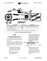
A
TAB
D
THUMB (pushing on link end)
B
LINK END
E
TOP VIEW: tab pivoting into link slot
C
THUMB (pushing on tab)
F
TOP VIEW: twist tab to lock the link in place
Figure 5-5: Attaching Compressor Belt Link
E
C
D
C
D
A
B
3
2
1
B
A
90°
F
KEY
DESCRIPTION
KEY
DESCRIPTION
1
Start at bottom edge of compressor pulley: Set belt into
groove, and grasp both the belt and the pulley edge
3
E
Hold the belt firm enough so that it does not
slip from the engine pulley. Move the belt to
align with the compressor pulley groove as it
is being rotated.
2
Rotate the pulley clockwise, while still holding the belt in
place.
Figure 5-6: Compressor Drive V-Belt Removal/Attachment
3
2
1
Sections 5.5.2.4
through
5.5.2.6
to size and assemble the belt.
2. The belt should be linked as a
completed loop prior to setting it
onto the pulley tracks. Run belt
around the proper belt groove on
the engine pulley (compressor
belt tracks to
outside
engine
pulley), taking care that the belt’s
tabs are facing inward toward the
pulley, and the arrows on the belt
point in the same direction as the


