background image

www.vanco1.com

800.626.6445

12

TROUBLE-SHOOTING

1.  Best results are usually achieved when the source and display resolutions are the same. If resolutions differ, the 

extenders will try to adjust the signal to match the resolution of the HDTV with the lowest resolution. This will result in a 
picture with a lower resolution on the other HDTV sets.

2.  If you do not get audio and video, access the “setup” menu on the TV to adjust the audio and video settings. If the HDMI 

control circuit cannot establish a handshake, then there usually will be no audio or video in addition to a blue or black 
screen with a statement similar to “this protocol not supported” or “weak signal”.

3.  If the above mentioned messages display, reset the receiver by disconnecting the power supply. You can also disconnect 

all of the HDMI and power cables, wait 15 minutes for any voltages to decay and then reconnect all of the cables.

4.  If you are still encountering issues, attempt the “hot-plug concept. With all of the HDMI cables disconnected, turn on 

the source and plug in the HDMI cable into it’s output, then power up the Vanco unit and plug the HDMI cable into it’s 
input, finally turn on the display and plug the HDMI cable from the receiver into it. This activates all of the devices in 
corresponding order and results in a signal being plugged into a device that is on and will attempt to connect the signal.

5.  Most of the major source and display manufacturers employ a proprietary control channel to communicate between 

devices from the same manufacturer. Sometimes this can interfere with the HDMI control circuit or the authentication 
of the signal. Call the manufacturer if you experience this issue. Sometimes a player, an audio/video receiver, or a cable/
satellite box may not have the latest software update, usually this can be downloaded from the manufacturer’s website.
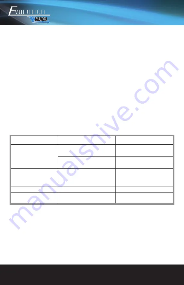
Problems

Potential Causes

Solutions

Color losing or no video signal 

output in HDMI display

The connecting cables may not be 

connected correctly or may be broken

Check whether the cables are connected 

correctly and in working condition

The display is not compatible with the 

present output resolution

Make sure the resolution of the display(s) 

is compatible with the present resolution

No HDMI signal output while local 

HDMI input is in normal working 

state

The connecting cables may not be 

connected correctly or it may be broken

Check whether the cables are connected 

correctly and in working condition

Splash screen in output devices

Poor quality of the connecting cable

Change for another cale of good quality

Static becomes stronger when 

connection the video connectors

Bad grounding

Check the grounding and make sure it is 

connected well

Summary of Contents for Evolution EV4K7014

Page 1: ...Vanco Part Number EV4K7014 4K 1x4 HDMI Splitter over Cat6 Cable with HDMI Loop Out www vanco1 com 800 626 6445 4K 1x4 HDMI Splitter over Cat6 Cable with HDMI Loop out ...

Page 2: ...cularly at the plugs 9 Use unit only with accessories specified by the manufacturer 10 Refer all servicing to qualified personnel CAUTION HDMI is a very complex technology requiring continuous authentication of the signal and the same video resolution and audio settings on all electronic equipment in the system When there are multiple sources and displays the video resolution and audio setting on ...

Page 3: ...ve distance and or resolution expectations FEATURES Evolution 4K 1x4 HDMI Splitter over Cat6 Cable with HDMI Loop out Part EV4K7014 Allows a single source to be split and extended to multiple displays Complete kit with 4 PoE Receivers included Features an additional HDMI output which can be used for a local display or to cascade to another splitter for a larger distribution system Transmission Ran...

Page 4: ...and HDR10 up to 230ft 70m 1080P 60Hz up to 330ft 100m Audio Formats PCM Dolby True HD and DTS master HDMI Interface Standard HDMI 2 0b HDCP 1 4 2 2 Remote IR 20 60KHZ wide frequency carrier ESD Level HBM 4kv contact discharge Temperature Range 0 60 degrees Celsius Operate 20 70 degrees Celsius Compliance FCC CE RoHS 1 EV4K7014 1x4 Splitter 4 EV4K7014 PoE Receivers 1 IR Blaster 4 IR Receivers displ...

Page 5: ... Connect to receivers with Cat6 cabling Note Home run cabling strongly recommended without any couplings punch downs or patch panels Cat5e not recommended 6 HDMI Output Port Connect to an HDMI display or connect to an additional EV4K7014 to cascade to create additional outputs 7 HDMI Input Port Connect an HDMI source device 8 EDID Dip Switch Set output compatibility resolution 9 RS 232 Port Connec...

Page 6: ...MI signal the indicator will emit solid blue 4 DC 12V Port No power supply needed splitter will provide power over Cat6 PoE to the receiver units 5 S PDIF OUT Digital Optical Audio break out that will output source signal audio connect to an external amplifier soundbar and or audio distribution component 6 HDMI OUT Connect a display such as an HDTV or HD Projector 7 IR IN Connect the included IR R...

Page 7: ...7014 RX Receivers 3 Connect displays such as an HDTV or HD Projector to the HDMI output of the EV4K7014 RX Receivers 4 Optional Connect a display such as an HDTV or HD Projector to the HDMI output of the EV4K7014 or connect an additional EV4K7014 to cascade to create additional outputs 5 For power connect the provided power supply HDTV IR Blaster HDTV HDMI HDMI HDMI HDMI HDMI HDMI Source HDTV HDTV...

Page 8: ...ere are 16 built in EDIDs in the product which can be adjusted via the DIP switches The upward DIP switch indicates 1 and the downward DIP switch indicates 0 After the adjustment is made power cycle the EV4K7014 View displays for changes ...

Page 9: ...800 626 6445 9 RS 232 CONTROL The default configuration is as follows Baud rate 9600 Data bits 8 Stop bits 1 Parity 0 ...

Page 10: ...play s from the splitter location see To Control the Displays section Additional IR receivers EVIR4K70 RX and IR blasters EVIR4K70 TX are sold separately To Control the Source 1 Plug the IR blaster into the IR OUT port of the splitter unit place blaster in front of the IR eye of the source 2 Plug the IR Receiver into the IR IN Port of the receiver unit place receiver at or near display ...

Page 11: ...g the IR receiver into the IR IN port of the splitter unit place receiver in a location where it can receive display IR commands 2 Plug the IR blaster into the IR OUT port of the receiver unit place blaster in front of the IR eye of the display s ...

Page 12: ... in corresponding order and results in a signal being plugged into a device that is on and will attempt to connect the signal 5 Most of the major source and display manufacturers employ a proprietary control channel to communicate between devices from the same manufacturer Sometimes this can interfere with the HDMI control circuit or the authentication of the signal Call the manufacturer if you ex...

Page 13: ... free from defects in materials and workmanship for a period of two years from the date of purchase Should this product in Vanco s opinion prove defective within this warranty period Vanco at its option will repair or replace this product without charge Any defective parts replaced become the property of Vanco This warranty does not apply to those products which have been damaged due to accident u...

Page 14: ...ons For additional information such as helpful installation videos etc please visit www vanco1 com LIABILITY STATEMENT Every effort has been made to ensure that this product is free of defects The manufacturer of this product cannot be held liable for the use of this hardware or any direct or indirect consequential damages arising from its use It is the responsibility of the user and installer of ...

Page 15: ...800 626 6445 15 ...

Page 16: ...Vanco International 506 Kingsland Drive Batavia Illinois 60510 call 800 626 6445 fax 630 879 9189 visit www vanco1 com ...

Reviews: