

© 2017 Vanderbilt
1 / 4
021_AGB800_I-200253_EN
Acoustic Glass Break Detector
Instruction and installation manual
AGB800
EC DECLARATION OF CONFORMITY
Hereby, Vanderbilt International (IRL) Ltd declares that this
equipment is in compliance with all relevant EU Directives for
CE marking. From 20/04/2016 it is in compliance with Directive
2014/30/EU (Electromagnetic Compatibility Directive).
The full text of the EU declaration of conformity is available at:
http://pcd.vanderbiltindustries.com/doc/intrusionaccessories
DESCRIPTION
AGB800 is an acoustic glass break detector giving an alarm
when glass is smashed at intruder attempts through windows,
doors and glazed walls.
The detector is based on advanced microcontroller technology
and programmed to take a lot of relevant acoustic factors into
account: The Digital Room Compensation (DRC). This makes
the detector able to distinguish between a true glass break and
other irrelevant sounds.
The detector is for indoor use. The coverage distance is 1
–9 m.
The coverage angle is 165º, which means that one detector can
protect several windows in the same room. The detector can
be mounted in the ceiling or on a wall with a free “line-of-sight”
to the window being protected.
AGB800 is certified according to EN 50131-2-7-1:2012, se-
curity grade 2.
Coverage area in the acoustic room Zone 1
–3
CONNECTION TO A 24-HOUR LOOP
The detector is constructed for continuous supervision and is
extra resistant to different acoustic disturbances. It will function
well in most environments. However in rooms with very high
rates of disturbances as in industrial workshops and gyms, it is
recommended to test the detector for 3
–4 weeks before decid-
ing to use it continuously. In rare cases a combination of ran-
dom sounds can trigger an alarm.
SIGNALLED EVENTS
Detector has two relays and one micro-switch to signal de-
tected and processed events to control panel in prioritised order
as following signals:
Glass break
– signalled by INTRUSION relay
Sabotage is signaled independently by TAMPER micro-
switch.
Event
Signal sent by relay or micro-switch
INTRUSION
TAMPER
No stimulus
Closed
Closed
Intrusion
OPEN
Closed
Tamper
Closed
OPEN
SPECIAL TOOLS
In most rooms (e.g. offices) no special tools are required during
the installation. In rooms with complicated acoustics it is rec-
ommended to use the ADT700 tester. ADT700 can also be
used for function test and annual service.
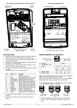
OPENING THE DETECTOR
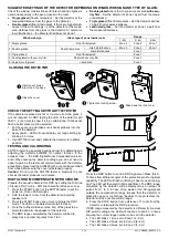
MOUNTING INSTRUCTIONS
Detector should be installed on a ceiling or on a wall oppo-
site to the glass to be protected
Clear
“line-of- sight” between the “microphone” of the de-
tector and the glass is required
Distance between the glass and the detector should be 1
–9m
Detector should be installed min. 50cm from a corner
Detector should be installed min. 1m over the floor
Detector should be installed min. 30cm from the ceiling (at
wall mounting)
Detector should be installed on a flat surface, which is free
from objects in a radius of 50cm from the detector
Detector should not be installed close to air vents or big
sound reflecting obstacles
Never mount the detector in the corners
Base
Cover
Cover
lock
LED
Microphone
Slide the lock cover up
Loosen the screw
Pull cover to open
min. 0.5 m
ma
x. 8
.5 m
max. 9 m
min. 0.3 m
min. 0.5 m
min.
1 m
Location for wall or ceiling mount


