
© 2017 Vanderbilt
2 / 4
021_AGB800_I-200253_EN
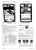
DETECTOR BASE AFTER REMOVAL OF THE COVER
INSTALLATION
1. Choose the best mounting position on the wall or ceiling.
2. Loosen the cover screw and remove the upper part
3. Use the bottom part as a template and mark the place of
the holes of with a pen
4. Use a 2.5mm drill for the self-tapping screws provided. If
necessary, use wall anchors
5. If necessary, cut
out the marked “knockout hole” on the
back of the base with a pair of tongs
6.
Pull the wiring cable through the “knockout hole” in the bot-
tom plate
7. Connect the wires to the screw terminals
Pin
Marking
Function
1
(-)
Ground
2
(+)
Plus 7 to 30 V DC
3
D/N
Day and Night control of LED
4
INTRUSION
INTRUSION relay output C
5
INTRUSION
INTRUSION relay output NC
6
Spare
Spare contact (unconnected)
7
FAULT
Spare contact (unconnected)
8
FAULT
Spare contact (unconnected)
9
Spare
Spare contact (unconnected)
10
TAMPER
Tamper switch output C
11
TAMPER
Tamper switch output NC
12
Spare
Spare contact (unconnected)
8. Use the cable strap provided to fix the wiring cable to the
detector.
9. Fix the detector firmly to the base with the enclosed
screws.
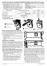
COVER SEEN FROM BELOW
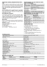
UNDERSTANDING THE DIP SWITCH
# Function
Setting
1
INTRUSION relay
mode
ON
–
Latch
OFF
– Auto
2 Range setting
4
–
9m
Zone1
2
–
4m
Zone 2
1
–2m
Zone 3
OFF
OFF
ON
ON
3 Range setting
OFF
ON
OFF
ON
DIP1=ON: INTRUSION relay mode ON means the INTRU-
SION relay will Latch and be open in alarm.
DIP1=OFF: INTRUSION relay mode OFF means the INTRU-
SION relay will be auto reset after 2 seconds in alarm.
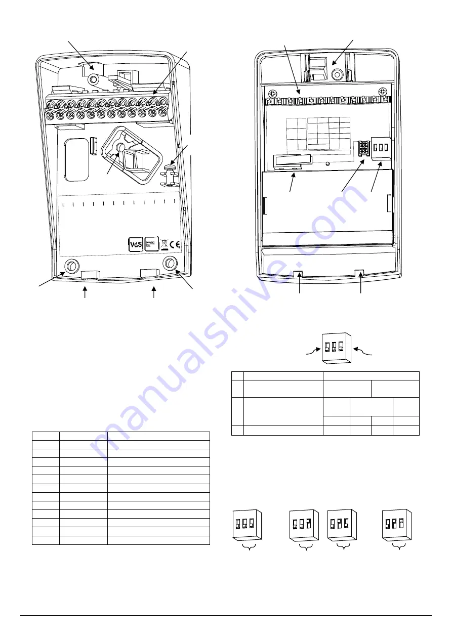
10. Set the desired range, i.e. the detector sensitivity setting
by using the DIP switch no 2 and 3.
11. Check the window constructions and note what kind of
glass is used and especially in the pane closest to the
room.
4
5
INTRUSION
7
8
10
11
TAMPER
1
(-)
2
(+)
3
D/N
6
9
12
Sp.
Sp.
Sp.
Sp.
Sp.
Acoustic Glass Break Detector
EN 50131-2-7-1 Security Grade 2
EN 50130-5 Environmental Class I
VdS 117503
AGB 800
Vanderbilt Intl (IRL) Ltd.
Clonshaugh Business Park
Clonshaugh, Dublin, D17 KV84
Ireland, V54535-Z130-A100
Mounting
hole #2
Slots for assembling
the cover hooks
Mounting
hole #3
Mounting
hole #1
Terminal
block
Cable jacket
“knock-out”
Cover
screw
Terminal block pins
Tamper
switch
DIP
switch
PC
interface
Hooks holding the cover to the base
Cover lock
A
G
B
8
00
P
C
in
te
rf
ac
e
U
SB
-l
in
k
12
Sp.
11
9
Sp.
7
Sp.
6
Sp.
1
(-)
2
(+)
3
D/N
8
Sp.
10
TAMPER
4
5
INTRUSION
DIP Switch Settings
Ac
ou
st
ic
G
la
ss
B
re
ak
D
et
ec
to
r
4-9 m
OFF
OFF
OFF
2
Range
3
ON
2-4 m
ON
OFF
ON
ON
1-2 m
Relay
mode
Latch
Auto
Reset
1
OFF
ON
D
IP
Sw
it
ch
1
2
Zone
Setting
3
ON
1 2 3
ON
1 2 3
INTRUSION relay
mode (DIP1)
Range setting
(DIP2, DIP3)
4
–9m, Zone 1
OFF, OFF
2
–4m, Zone 2
OFF, ON or ON,
OFF
1
–2m, Zone 3
ON, ON
ON
1 2 3
ON
1 2 3
ON
1 2 3
ON
1 2 3


