background image

WPIR-EXT 

                                                       Installation Instructions/User Manual 

Edition Date: 26.07.2021 


Doc ID: I-200478 

5. Installation and Discovery & Enrollment Process 


Select Mounting Location 

The installation of the WPIR-EXT requires a flat and secure mounting surface for the detector to perform correctly. 
The protected area must be free from obstacles like walls, fences, trees, ditches, and other microwave detectors, as 
well as systems of anti-intrusion surveillance. 
The back metal bracket enables WPIR-EXT installation on a level wall or pole.  
Choose a location most likely to intercept an intruder according to the detection pattern on page 6. 

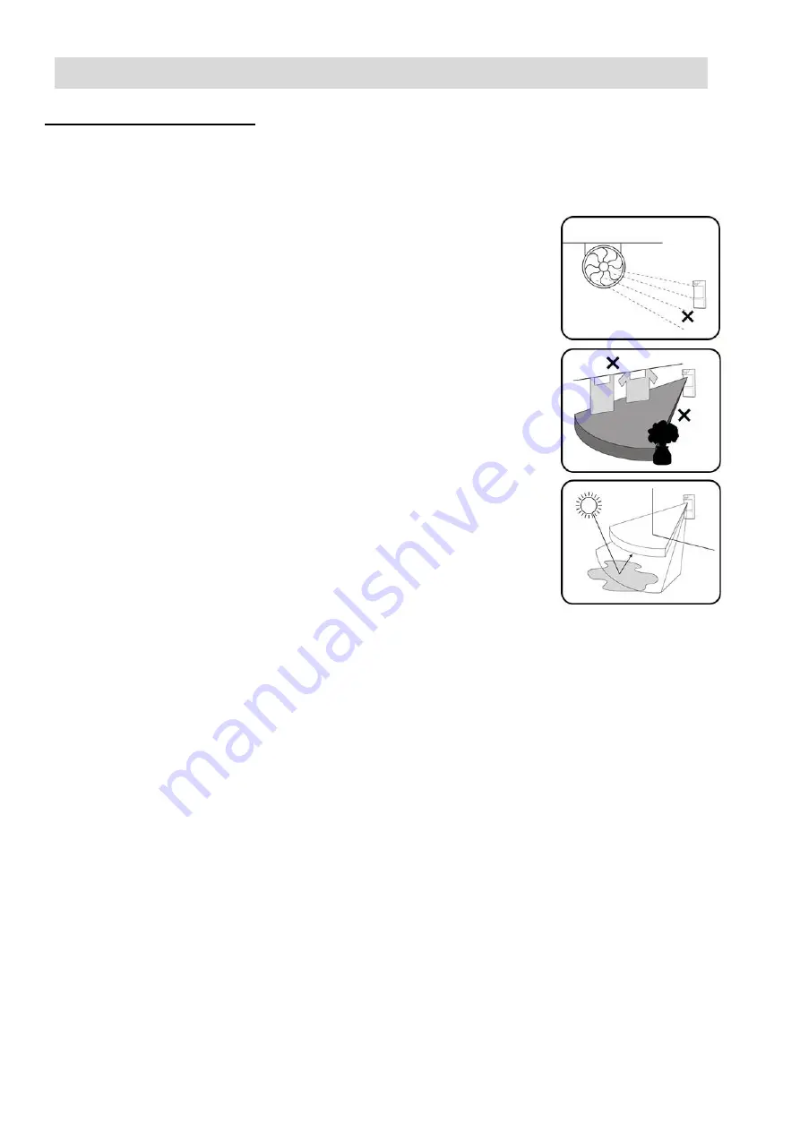
Avoid the following installation locations: 


Facing direct sunlight 


Facing areas subject to rapid temperature changes 


Wall angle of more than 10º from perpendicular line 


Mounting at more than 10º Deviation from horizontal line 


Facing metal doors 


Do not install near direct source of heat or air gust 


Clear all physical obstacles from the detection area (for example 
Plants, laundry, etc.) 


Clear all light reflecting surfaces from the detection area, as well as 
water puddles 


Avoid installation on the following types of ground: 
Thick vegetation, Grass (un-mown), Water, Sand, and Metal. 


NOTE:


Recommended installation height is 1.2m. 


If there is a risk of the protected area may contain tall pets (over 60cm), install the detector at a height of 
1.5m. 


The Double Quad high quality sensor detects motion crossing the beam; it is less sensitive detecting motion 
towards the detector. 


The WPIR-EXT performs best when provided with a constant and stable environment. 


To ensure suitable operation of the WPIR-EXT type of ground should be one of the following: Asphalt 
concrete, Cement, Soil, Clay, Gravel, or Grass (mown). 


Summary of Contents for WPIR-EXT

Page 1: ...WPIR EXT Two Way Wireless Outdoor Double PIR Detector with Anti masking INSTALLATION INSTRUCTIONS USER MANUAL Edition Date 01 11 2021 Doc ID I 200478...

Page 2: ...We reserve all rights in this document and in the subject thereof By acceptance of the document the recipient acknowledges these rights and undertakes not to publish the document nor the subject ther...

Page 3: ...duction 3 2 Features 3 3 Operation 4 4 Assembly Description 5 5 Installation and Discovery Enrollment Process 7 Select Mounting Location 7 6 Detector Installation 8 7 Discovery Enrollment Process 9 8...

Page 4: ...allation environment and protection site The WPIR EXT is designed to protect large areas and can easily be installed on walls toprovide a solid protection of the area while rejecting interference from...

Page 5: ...attery Low signal will be sent When Battery level drops below Cut Off level 2 3V the device will stop functioning and the Red LED will blink for 10 seconds and then turned Off TAMPER Whenever the cove...

Page 6: ...s a robust detector which includes indication LED prism that can be easily observed from long distance Having a back metal bracket the WPIR EXT can be easily mounted to walls and poles using mounting...

Page 7: ...al 6 Edition Date 26 07 2021 Doc ID I 200478 Front view Back view with battery 2 LED Detector 9 Battery Cover 4 Upper PIR Element 10 Back Tamper Switch Removal 5 Anti Mask Sensor 6 Lower PIR Element 7...

Page 8: ...than 10 from perpendicular line Mounting at more than 10 Deviation from horizontal line Facing metal doors Do not install near direct source of heat or air gust Clear all physical obstacles from the...

Page 9: ...the wall leaving 15cm from all sides for easy installation and maintenance 4 Install the metal bracket on the wall or a pole using either mounting screws or Jubilee clips metal bands 5 Install the det...

Page 10: ...o observe correct polarity Inserting the batteries starts the discovery process from the device III Enroll the device by configuring the Description Zone Zone Type and other settings in the SPC system...

Page 11: ...IR EXT Installation Instructions User Manual 10 Edition Date 26 07 2021 Doc ID I 200478 5 Close the battery cover DISCOVERY FAILED Remove the batteries wait for around 10 seconds and repeat the proces...

Page 12: ...and 180 In order to change the detection beam direction rotate the internal detection element housing to thedesired direction Detection range setting The WPIR EXT detection range may vary between 3m a...

Page 13: ...tempt is made to mask the lens with a sticker or to put a masking object close to the lens a troublealert will result up to 180 seconds after masking The Red LED will blink and the TROUBLE Tamper will...

Page 14: ...n to ALARM sound whenever motion is detected the red LED and the Buzzer also turns ONwhenever motion is detected 6 Allow 5 sec between each test for the detector to stabilize 7 Upon installation the u...

Page 15: ...ssion Alarm Anti Mask Tamper Supervision Low Battery Supervision Time 7 min by default configurable between 1 to 30 minutes Detection Range Configurable from 3m to 12m Installation Height From 0 8m to...

Reviews: