REV 7
ATRT-03, ATRT-03A, AND ATRT-03B USER’S MANUAL
iv
LIST OF TABLES
Table 1. ATRT-03 Technical Specifications ...................................................................................... 4
Table 2. ATRT-03A Technical Specifications ................................................................................... 5
Table 3. ATRT-03B Technical Specifications .................................................................................... 6
Table 4. Functional Descriptions of ATRT-03 Controls and Indicators ........................................... 8
Table 5. Functional Descriptions of ATRT-03A Controls and Indicators ....................................... 10
Table 6. Functional Descriptions of ATRT-03B Controls and Indicators ....................................... 12
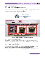
Table 7. Voltage Selection Jumper Settings .................................................................................. 13
Table 8. Descriptions of Single Phase Test Results Elements (Column Format) .......................... 38
Table 9. Descriptions of Single Phase Test Results Elements (Detailed Format) ......................... 39
Table 10. Descriptions of Dyn1 Test Results Elements (Column Format) .................................... 44
Table 11. Descriptions of Dyn1 Test Results Elements (Detailed Format) ................................... 46
LIST OF FIGURES
Figure 1. ATRT-03 Controls and Indicators ..................................................................................... 7
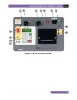
Figure 2. ATRT-03A Controls and Indicators ................................................................................... 9
Figure 3. ATRT-03B Controls and Indicators ................................................................................. 11
Figure 4. Voltage Selection Jumper Location and Settings ........................................................... 13
Figure 5. Typical Front Panel Cable Connections .......................................................................... 15
Figure 6. Typical H & X Cable Connections to a Delta-Wye Transformer ..................................... 16
Figure 7. Typical Connections to a Single Phase Transformer ...................................................... 17
Figure 8. Typical Connections to a Single Phase Auto Transformer ............................................. 17
Figure 9. Typical Connections to a Type A Voltage Regulator ...................................................... 18
Figure 10. Typical Connections to a Type B Voltage Regulator .................................................... 18
Figure 11. Typical Connections to a Donut Type (un-mounted) Current Transformer (CT) ......... 19
Figure 12. Typical Connections to a Multi-Tap Current Transformer ........................................... 20
Figure 13. Typical Connections to a Bushing Mount CT on a Single Phase Transformer ............. 21
Figure 14. Typical Connections to Bushing Mount CT's on Delta Transformer ............................ 22
Figure 15. Typical Connections to Bushing Mount CT's on Wye Transformer ............................. 23
Figure 16. Single Phase Test Results Printout - Column Format .................................................. 38
Figure 17. Single Phase Test Results Printout - Detailed Format ................................................. 39
Figure 18. Y to Delta Test Results Printout - Column Format ....................................................... 44
Figure 19. Y to Delta Test Results Printout - Detailed Format ...................................................... 45
Figure 20. Special Dy11 Transformer Test Printout ...................................................................... 52
Figure 21. Typical Test Record Directory Printout ........................................................................ 66
Figure 22. Test Plan Test Results Printout .................................................................................... 74
Figure 23. Sample Test Plan Printout ............................................................................................ 80
Summary of Contents for ATRT-03
Page 14: ...ATRT 03 ATRT 03A AND ATRT 03B USER S MANUAL REV 2 9 Figure 2 ATRT 03A Controls and Indicators...
Page 16: ...ATRT 03 ATRT 03A AND ATRT 03B USER S MANUAL REV 2 11 Figure 3 ATRT 03B Controls and Indicators...
Page 79: ...REV 2 ATRT 03 ATRT 03A AND ATRT 03B USER S MANUAL 74 Figure 22 Test Plan Test Results Printout...
Page 85: ...REV 2 ATRT 03 ATRT 03A AND ATRT 03B USER S MANUAL 80 Figure 23 Sample Test Plan Printout...
Page 91: ...REV 2 ATRT 03 ATRT 03A AND ATRT 03B USER S MANUAL 86...
Page 92: ...ATRT 03 ATRT 03A AND ATRT 03B USER S MANUAL REV 2 87...
Page 93: ...REV 2 ATRT 03 ATRT 03A AND ATRT 03B USER S MANUAL 88...
Page 94: ...ATRT 03 ATRT 03A AND ATRT 03B USER S MANUAL REV 2 89...
Page 95: ...REV 2 ATRT 03 ATRT 03A AND ATRT 03B USER S MANUAL 90...
Page 96: ...ATRT 03 ATRT 03A AND ATRT 03B USER S MANUAL REV 2 91...
Page 97: ...REV 2 ATRT 03 ATRT 03A AND ATRT 03B USER S MANUAL 92...
Page 99: ...REV 2 ATRT 03 ATRT 03A AND ATRT 03B USER S MANUAL 94...
Page 100: ...ATRT 03 ATRT 03A AND ATRT 03B USER S MANUAL REV 2 95...
Page 101: ...REV 2 ATRT 03 ATRT 03A AND ATRT 03B USER S MANUAL 96...
Page 102: ...ATRT 03 ATRT 03A AND ATRT 03B USER S MANUAL REV 2 97...
Page 103: ...REV 2 ATRT 03 ATRT 03A AND ATRT 03B USER S MANUAL 98...
Page 104: ...ATRT 03 ATRT 03A AND ATRT 03B USER S MANUAL REV 2 99...
Page 106: ...ATRT 03 ATRT 03A AND ATRT 03B USER S MANUAL REV 2 101...
Page 107: ...REV 2 ATRT 03 ATRT 03A AND ATRT 03B USER S MANUAL 102...
Page 108: ...ATRT 03 ATRT 03A AND ATRT 03B USER S MANUAL REV 2 103...
Page 109: ...REV 2 ATRT 03 ATRT 03A AND ATRT 03B USER S MANUAL 104...
Page 110: ...ATRT 03 ATRT 03A AND ATRT 03B USER S MANUAL REV 2 105...
Page 111: ...REV 2 ATRT 03 ATRT 03A AND ATRT 03B USER S MANUAL 106...


