background image

ATRT-03, ATRT-03A, AND ATRT-03B USER’S MANUAL

REV 2


49


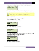
Press the 

[ENTER]

 key. 

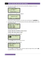
The following screen will be displayed: 


Type the X winding name plate voltage value using the numeric keypad. The 
screen will be updated as shown below: 


Press the 

[ENTER]

 key. 

Continue to step e.


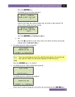
2.


NO 

Press the 

[2]

 key (

NO

) if you do not want to enter the transformer name plate 

voltage values. 

Continue to step e.


e.


The following screen will be displayed: 


NOTE 

This screen and subsequent screens will differ depending on the transformer 
type selected. Follow any instructions displayed on the LCD screen. 

Press the 

[START]

 key to run the test. 

f.


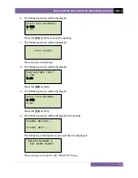
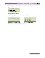
The following screen will be displayed temporarily: 


The following screen will then be displayed: 


Follow the instructions displayed on the LCD screen and then press the 

[ENTER]

 key. 


JUMPER H1-H3 


“ENTER” to CONTINUE 

Dy11 XFMR 


PLEASE WAIT... 

Dy11 XFMR 

JUMPER H2-H3 


“START” to RUN TEST 

  ENTER X WINDING
NAME-PLATE VOLTAGE: 
         100 V 
 

  ENTER X WINDING
NAME-PLATE VOLTAGE: 
             V 
 

Summary of Contents for ATRT-03

Page 1: ...03A and ATRT 03B THREE PHASE TRANSFORMER TURNS RATIO METERS USER S MANUAL Vanguard Instruments Company Inc 1520 S Hellman Ave Ontario California 91761 USA TEL 909 923 9390 FAX 909 923 9391 August 201...

Page 2: ...r test shall be off line and fully isolated Always ground the ATRT 03 03A 03B to a substation ground before connecting the test cables to a transformer Do not perform test procedures or service unless...

Page 3: ...ate and Time 26 3 4 Enabling the Computer Interface 27 3 5 Using the Turns Ratio Calculator 28 3 6 Performing Tests 30 3 6 1 Entering Test Record Header Information 30 3 6 2 Testing a Single Phase Tra...

Page 4: ...ER S MANUAL REV 7 iii APPENDIX A TRANSFORMER VECTOR GROUP CODES 84 APPENDIX B Common ANSI Transformer Descriptions 85 APPENDIX C CEI IEC 60076 1 Transformer Descriptions 93 APPENDIX D Australian Std 2...

Page 5: ...ont Panel Cable Connections 15 Figure 6 Typical H X Cable Connections to a Delta Wye Transformer 16 Figure 7 Typical Connections to a Single Phase Transformer 17 Figure 8 Typical Connections to a Sing...

Page 6: ...ey switch or knob on the ATRT is indicated as KEY SWITCH KNOB Menu names are referenced as MENU NAME ATRT LCD screen output is shown as When instructions are provided the menu item that should be sele...

Page 7: ...ross the unloaded transformer windings To ensure accuracy the ATRT 03 s measuring circuitry self calibrates before each measurement It requires neither adjustment nor temperature compensation The ATRT...

Page 8: ...9 turns ratio excitation current phase angle and nameplate voltage readings Test records can be recalled locally or transferred to a PC via the RS 232C interface Computer Interface The ATRT 03 can be...

Page 9: ...ble in bright sunlight and low light levels PRINTER Built in 4 5 inch wide thermal printer COMPUTER INTERFACE RS 232C 19 200 baud port PC SOFTWARE Windows XP Vista based Transformer Turns Ratio Analyz...

Page 10: ...Characters by 4 Lines Viewable in bright sunlight and low light levels PRINTER Built in 4 5 inch wide thermal printer COMPUTER INTERFACE RS 232C 19 200 baud port PC SOFTWARE Windows XP Vista based Tr...

Page 11: ...Viewable in bright sunlight and low light levels COMPUTER INTERFACE RS 232C 19 200 baud port PC SOFTWARE Windows XP Vista based Transformer Turns Ratio Analyzer application is included with purchase...

Page 12: ...indicator which is cross referenced to a functional description in the corresponding table The purpose of the controls and indicators may seem obvious but users should familiarize themselves with the...

Page 13: ...3 X X voltage connector 4 4 5 inch wide thermal printer 5 120 240 Vac 1A 50 60Hz Fuse 250Vac 2A Fast Blow Input power connector and fused power switch with third wire safety ground 6 Ground stud for...

Page 14: ...ATRT 03 ATRT 03A AND ATRT 03B USER S MANUAL REV 2 9 Figure 2 ATRT 03A Controls and Indicators...

Page 15: ...nter 5 POWER Power switch 6 120 240 Vac 1A 50 60Hz Fuse 250Vac 2A Fast Blow Input power connector with third wire safety ground 7 GROUND Ground stud for connecting to sub station ground 8 CHARGE LED i...

Page 16: ...ATRT 03 ATRT 03A AND ATRT 03B USER S MANUAL REV 2 11 Figure 3 ATRT 03B Controls and Indicators...

Page 17: ...voltage connector 3 X X voltage connector 4 120 240 Vac 1A 50 60Hz Fuse 250Vac 2A Fast Blow Input power connector and fused power switch with third wire safety ground 5 Ground stud for connecting to...

Page 18: ...220 240 Vac Pin 2 3 Figure 4 Voltage Selection Jumper Location and Settings 2 2 ATRT 03A Operating Voltages The ATRT 03A uses a special switching power supply The input AC receptacle can accept volta...

Page 19: ...ilt in thermal printers use 4 5 inch wide thermal paper for printing test results To maintain the highest print quality and to avoid paper jams the use of thermal paper supplied by Vanguard Instrument...

Page 20: ...be grounded before connecting test leads to the transformer This will prevent inducing any voltages into the ATRT 03 All transformer bus connections must be removed and the transformer must be isolate...

Page 21: ...REV 2 ATRT 03 ATRT 03A AND ATRT 03B USER S MANUAL 16 3 1 2 Typical Connections to a Delta Wye Transformer Figure 6 Typical H X Cable Connections to a Delta Wye Transformer...

Page 22: ...AND ATRT 03B USER S MANUAL REV 2 17 3 1 3 Typical Connections to a Single Phase Transformer Figure 7 Typical Connections to a Single Phase Transformer Figure 8 Typical Connections to a Single Phase A...

Page 23: ...03 ATRT 03A AND ATRT 03B USER S MANUAL 18 3 1 4 Typical Connections to a Voltage Regulator Figure 9 Typical Connections to a Type A Voltage Regulator Figure 10 Typical Connections to a Type B Voltage...

Page 24: ...V 2 19 3 1 5 Typical Connections to a Donut Type un mounted Current Transformer Figure 11 Typical Connections to a Donut Type un mounted Current Transformer CT NOTE The H and X test leads are reversed...

Page 25: ...REV 2 ATRT 03 ATRT 03A AND ATRT 03B USER S MANUAL 20 3 1 6 Typical Connections to a Multi Tap Current Transformer Figure 12 Typical Connections to a Multi Tap Current Transformer...

Page 26: ...3 ATRT 03A AND ATRT 03B USER S MANUAL REV 2 21 3 1 7 Typical Connections to a Bushing Mount CT on a Single Phase Transformer Figure 13 Typical Connections to a Bushing Mount CT on a Single Phase Trans...

Page 27: ...RT 03B USER S MANUAL 22 3 1 8 Typical Connections to Bushing Mount CT s on Delta Transformer Figure 14 Typical Connections to Bushing Mount CT s on Delta Transformer NOTE The CT turns ratio is obtaine...

Page 28: ...3B USER S MANUAL REV 2 23 3 1 9 Typical Connections to Bushing Mount CT s on Wye Transformer Figure 15 Typical Connections to Bushing Mount CT s on Wye Transformer NOTE The CT turns ratio is obtained...

Page 29: ...n noisy environments Follow the steps below to set the test voltage NOTE Pressing the STOP key at any time will return you to the START UP menu a Turn on the unit and start from the START UP menu Pres...

Page 30: ...ATRT 03A AND ATRT 03B USER S MANUAL REV 2 25 e The voltage will be set and the following confirmation message will be displayed Press any key to return to the START UP menu TEST VOLTAGE SET TO 40 VOL...

Page 31: ...d The following screen will be displayed Using the alpha numeric keypad enter the date and time in the format shown on the screen You do not need to enter dashes or colons When the complete date and...

Page 32: ...owing screen will be displayed Press the 4 key NEXT PAGE c The following screen will be displayed Press the 1 key COMPUTER CONTROL d The following screen will be displayed You can now use the TTRA sof...

Page 33: ...on the keypad For this example press the 3 key to select the Y dT transformer type c The following screen will be displayed Type the H name plate voltage value using the keypad and then press the ENTE...

Page 34: ...ATRT 03 ATRT 03A AND ATRT 03B USER S MANUAL REV 2 29 Press any key to return to the START UP menu...

Page 35: ...be displayed Type the company name using the alpha numeric keypad When pressing a key the corresponding number on the key will be displayed first Pressing the key again will display the first letter...

Page 36: ...ing the alpha numeric keypad and then press the ENTER key g The following screen will be displayed Type the transformer s model information using the alpha numeric keypad and then press the ENTER key...

Page 37: ...meric keypad and then press the ENTER key j The following screen will be displayed Type the operator s name using the alpha numeric keypad and then press the ENTER key All header information will be s...

Page 38: ...displayed instead of the above screen Press the 3 key if you would like to use the name plate voltage values from the previous test performed and then continue to step d See below for details about o...

Page 39: ...ress the ENTER key Continue to step d 2 NO Press the 2 key NO if you do not want to enter the transformer name plate voltage values Continue to step d d The following screen will be displayed Press th...

Page 40: ...atio x 100 Press any key to continue If using an ATRT 03 or ATRT 03A continue to step f If using an ATRT 03B continue to step h f The following screen will be displayed Press the 1 key YES to print th...

Page 41: ...l be displayed instead Press the 1 key APPEND PREV DATA to append the data in the unit s working memory to the current test results or press the 2 key CLEAR PREV DATA to clear any previous data from t...

Page 42: ...ash EEPROM l The following screen will be displayed momentarily The following confirmation screen will then be displayed NOTE The unit will automatically assign the record number and will not over wri...

Page 43: ...ase Test Results Elements Column Format Item Number Description 1 Test record date and time 2 Test record header information see section 3 6 1 3 Test voltage 4 Type of transformer under test 5 H tap v...

Page 44: ...e Test Results Elements Detailed Format Item Number Description 1 Test record date and time 2 Test record header information see section 3 6 1 3 Test voltage 4 Type of transformer under test 5 H tap v...

Page 45: ...The following screen will be displayed NOTE If you had entered name plate voltages for a previous test the following screen will be displayed instead of the above screen Press the 3 key if you would l...

Page 46: ...value using the numeric keypad The screen will be updated as shown below Press the ENTER key Continue to step e 2 NO Press the 2 key NO if you do not want to enter the transformer name plate voltage...

Page 47: ...e C test results as shown Press any key to continue If using an ATRT 03 or ATRT 03A continue to step g If using an ATRT 03B continue to step i g The following screen will be displayed Press the 1 key...

Page 48: ...1 key YES to save the reading j The following screen will be displayed Press any key to continue k The following screen will be displayed Press the 2 key NO l The following screen will be displayed P...

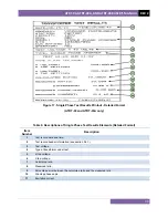
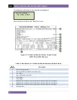
Page 49: ...ts Column Format Item Number Description 1 Test record date and time 2 Test record header information see section 3 6 1 3 Test voltage 4 Type of transformer under test 5 H tap voltage 6 X tap voltage...

Page 50: ...ATRT 03 ATRT 03A AND ATRT 03B USER S MANUAL REV 2 45 Figure 19 Y to Delta Test Results Printout Detailed Format ATRT 03 and ATRT 03A only...

Page 51: ...ase angle 14 H1 H0 X1 X2 measured excitation current 15 Test H2 H0 and X2 X3 section heading 16 H2 H0 tap voltage 17 X2 X3 tap voltage 18 H2 H0 X2 X3 calculated ratio 19 H2 H0 X2 X3 measured ratio 20...

Page 52: ...The following screen will be displayed Press the 6 key SP TEST c The following screen will be displayed 1 ENTER SP TEST NUM Press the 1 key ENTER SP TEST NUM to enter the special test number Please s...

Page 53: ...test the following screen will be displayed instead of the above screen Press the 3 key if you would like to use the name plate voltage values from the previous test performed and then continue to ste...

Page 54: ...e The following screen will be displayed NOTE This screen and subsequent screens will differ depending on the transformer type selected Follow any instructions displayed on the LCD screen Press the S...

Page 55: ...screen temporarily as shown Press any key to continue If using an ATRT 03 or ATRT 03A continue to step i If using an ATRT 03B continue to step k i The following screen will be displayed Press the 1 ke...

Page 56: ...g screen will be displayed Press the 2 key NO n The following screen will be displayed Press the 1 key YES o The following screen will be displayed momentarily The following confirmation screen will t...

Page 57: ...REV 2 ATRT 03 ATRT 03A AND ATRT 03B USER S MANUAL 52 Figure 20 Special Dy11 Transformer Test Printout...

Page 58: ...the LCD screen Continue to step e NOTE The initial screen will display the last transformer type that was tested using the Quick Test mode If a test has not been performed yet the default is a single...

Page 59: ...s shown below Press the ENTER key The following screen will be displayed Type the X winding name plate voltage value using the numeric keypad The screen will be updated as shown below Press the ENTER...

Page 60: ...he 1 key START TEST e The ATRT 03 will perform the selected test and display the test results on the LCD screen as shown below Single Phase Test Results Example Y dT Test Results Example Press any key...

Page 61: ...es Follow the steps below to test a three phase transformer using the auto detect mode a Start from the START UP menu Press the 4 key DIAG b The following screen will be displayed Press the 3 key AUTO...

Page 62: ...e the transformer type has been determined the unit will start performing the test f The screen will be updated with the test results as shown Press any key to continue If using an ATRT 03 or an ATRT...

Page 63: ...g screen will be displayed Press the 2 key NO l The following screen will be displayed Press the 1 key YES m The following screen will be displayed momentarily The following confirmation screen will t...

Page 64: ...ECORD c The following screen will be displayed Press the 1 key RESTORE RECORD d The following screen will be displayed 1 ENTER RECORD NUMBR Press the 1 key ENTER RECORD NUMBR if you know the record nu...

Page 65: ...test record data on the unit s LCD screen Continue to step 1 4 Press the 2 key PRINT TEST RECORD to print the restored test record data on the unit s built in thermal printer The following screen wil...

Page 66: ...TEST RECORD to scroll through a directory of the stored test records 2 1 The following screen will be displayed Press the PAPER Contrast button or the PAPER Contrast key to display the next or previou...

Page 67: ...step c If using an ATRT 03B continue to step d c The following screen will be displayed Press the 1 key SCROLL TEST RECORD to display the test record data on the unit s LCD screen Continue to step d P...

Page 68: ...wn below Press the PAPER Contrast key The test record details will be displayed as shown below Press the PAPER Contrast key again to view the test data Press the STOP key to return to the START UP men...

Page 69: ...TRT 03B continue to step e d The following screen will be displayed Press the 1 key FULL DIRECTORY to print a directory of all the test records stored in the unit s Flash EEPROM The directory will be...

Page 70: ...APER Contrast key to scroll through the test record directory The test record header information will be displayed as shown below Press the STOP key when you are down browsing through the test record...

Page 71: ...REV 2 ATRT 03 ATRT 03A AND ATRT 03B USER S MANUAL 66 Figure 21 Typical Test Record Directory Printout...

Page 72: ...ERASE RECORDS d The following screen will be displayed 1 ERASE SINGLE REC Press the 1 key ERASE SINGLE REC to erase a single test record from the unit s internal Flash EEPROM The following screen will...

Page 73: ...You will be returned to START UP menu 2 ERASE ALL RECORDS Press the 2 key ERASE ALL RECORDS to erase all the test records from the unit s internal Flash EEPROM The following warning screen will be dis...

Page 74: ...est Plan Follow the steps below to perform a test using a test plan a Start from the START UP menu Press the 2 key SETUP b The following screen will be displayed Press the 4 key NEXT PAGE c The follow...

Page 75: ...o scroll through a directory of the test plans stored in the unit s Flash EEPROM The following screen will be displayed Press either the PAPER Contrast or PAPER Contrast key to scroll forward or rever...

Page 76: ...llowing screen will be displayed Press the 1 key NO i The following screen will be displayed Set the transformer to the tap position indicated on the LCD screen Press the START key to run the test usi...

Page 77: ...displayed Press the 1 key YES to print the test results l The following screen will be displayed Press the 1 key COLUMN to print a columnar report or press the 2 key DETAILED to print a detailed repor...

Page 78: ...test plan has been performed Press any key to continue q The following screen will be displayed Press the 1 key YES to save the test record to the unit s Flash EEPROM r The following screen will be di...

Page 79: ...REV 2 ATRT 03 ATRT 03A AND ATRT 03B USER S MANUAL 74 Figure 22 Test Plan Test Results Printout...

Page 80: ...yed Press the 4 key TEST PLANS d The following screen will be displayed Press the 2 key UNLOAD TEST PLAN e The test plan will be unloaded from the working memory and the following screen will be displ...

Page 81: ...Press the 4 key TEST PLANS d The following screen will be displayed Press the 3 key PLAN DIRECTORY If using an ATRT 03 or ATRT 03A the test plan directory will be printed on the built in thermal print...

Page 82: ...PER Contrast or PAPER Contrast key to scroll forward or reverse through the test plan directory The test plan header will be displayed Press the STOP key when you are done browsing the test plan direc...

Page 83: ...following screen will be displayed Press the 4 key NEXT PAGE c The following screen will be displayed Press the 4 key TEST PLANS d The following screen will be displayed Press the 4 key PRINT TEST PLA...

Page 84: ...key SCROLL TO SELECT to select a test plan by scrolling through the test plan directory The following screen will be displayed Press either the PAPER Contrast or PAPER Contrast key to scroll forward o...

Page 85: ...REV 2 ATRT 03 ATRT 03A AND ATRT 03B USER S MANUAL 80 Figure 23 Sample Test Plan Printout...

Page 86: ...ayed Connect the H and X cables per the on screen instructions and press the ENTER key d The following screen will be displayed while the cables are being tested The screen will be updated with the st...

Page 87: ...ons and then press the ENTER key d The ATRT 03 will start performing a DELTA DELTA test The following screen will be displayed momentarily The screen will then be updated with the test results for eac...

Page 88: ...REV 2 83 The screen will then be updated with the test results for each phase NOTE The ratio reading should be 1 0000 0 1 for all tests Press any key to return to the START UP menu RATIO mA DIFF 1 00...

Page 89: ...bols denoting lower or intermediate voltage ratings will be in lower case letters If the neutral point of either a wye or zig zag winding is brought out the indication will be an N high voltage or n l...

Page 90: ...ATRT 03 ATRT 03A AND ATRT 03B USER S MANUAL REV 2 85 APPENDIX B Common ANSI Transformer Descriptions...

Page 91: ...REV 2 ATRT 03 ATRT 03A AND ATRT 03B USER S MANUAL 86...

Page 92: ...ATRT 03 ATRT 03A AND ATRT 03B USER S MANUAL REV 2 87...

Page 93: ...REV 2 ATRT 03 ATRT 03A AND ATRT 03B USER S MANUAL 88...

Page 94: ...ATRT 03 ATRT 03A AND ATRT 03B USER S MANUAL REV 2 89...

Page 95: ...REV 2 ATRT 03 ATRT 03A AND ATRT 03B USER S MANUAL 90...

Page 96: ...ATRT 03 ATRT 03A AND ATRT 03B USER S MANUAL REV 2 91...

Page 97: ...REV 2 ATRT 03 ATRT 03A AND ATRT 03B USER S MANUAL 92...

Page 98: ...ATRT 03 ATRT 03A AND ATRT 03B USER S MANUAL REV 2 93 APPENDIX C CEI IEC 60076 1 Transformer Descriptions...

Page 99: ...REV 2 ATRT 03 ATRT 03A AND ATRT 03B USER S MANUAL 94...

Page 100: ...ATRT 03 ATRT 03A AND ATRT 03B USER S MANUAL REV 2 95...

Page 101: ...REV 2 ATRT 03 ATRT 03A AND ATRT 03B USER S MANUAL 96...

Page 102: ...ATRT 03 ATRT 03A AND ATRT 03B USER S MANUAL REV 2 97...

Page 103: ...REV 2 ATRT 03 ATRT 03A AND ATRT 03B USER S MANUAL 98...

Page 104: ...ATRT 03 ATRT 03A AND ATRT 03B USER S MANUAL REV 2 99...

Page 105: ...REV 2 ATRT 03 ATRT 03A AND ATRT 03B USER S MANUAL 100 APPENDIX D Australian Std 2374 Transformer Descriptions...

Page 106: ...ATRT 03 ATRT 03A AND ATRT 03B USER S MANUAL REV 2 101...

Page 107: ...REV 2 ATRT 03 ATRT 03A AND ATRT 03B USER S MANUAL 102...

Page 108: ...ATRT 03 ATRT 03A AND ATRT 03B USER S MANUAL REV 2 103...

Page 109: ...REV 2 ATRT 03 ATRT 03A AND ATRT 03B USER S MANUAL 104...

Page 110: ...ATRT 03 ATRT 03A AND ATRT 03B USER S MANUAL REV 2 105...

Page 111: ...REV 2 ATRT 03 ATRT 03A AND ATRT 03B USER S MANUAL 106...

Page 112: ...ellman Ave Ontario CA 91761 USA Phone 909 923 9390 Fax 909 923 9391 www vanguard instruments com Copyright 2010 by Vanguard Instruments Company Inc ATRT 03 03A 03B User s Manual Revision 2 0 August 26...

Reviews: