Assembly
Assembly
Assembly
Assembly
Assembly
9
20
Microscope Use
Microscope Use
Microscope Use
Microscope Use
Microscope Use
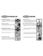
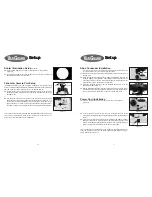
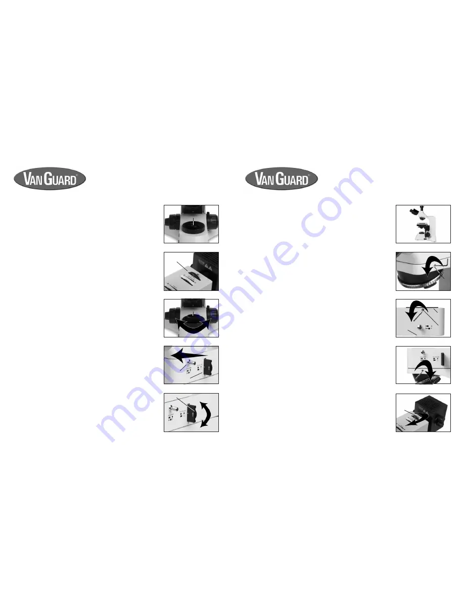
Figure 52
Figure 53
Figure 54
Figure 55
Figure 56
Colored Filters - Transmitted
6.
The transmitted Kohler light illuminator features a drop-in filter holder (figure
52) for use with the included colored absorption filters. These filters can be
used for color correction and image enhancement during photomicrography
and general use. The filters can be used alone or stacked in order to achieve
desired results.
Colored Filters - Reflected
7.
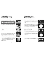
The reflected illuminator features a filter wheel (figure 53) containing colored
absorption filter settings, a dispersion filter, and an open setting. As with the
transmitted filters they are used for color correction and image enhancement.
Polarizer/Analyzer - Transmitted
8.
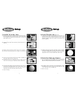
Simple polarization is possible when utilizing the polarizer function in order to
enhance contrast in certain types of specimens. The transmitted illuminator
uses a removable polarizer that can be placed on top of the Kohler light field
diaphragm (figure 54). The filter is then rotated to the desired level of extinction.
Polarizer/Analyzer - Reflected
10.
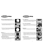
As with the transmitted polarizer, the reflected illumination also features a
simple polarization function. Located at the right side of the reflected
illuminator is the analyzer knob which must be pushed inward as well as the
polarizer slider (figure 56). Polarization is achieved by turning the rotation
wheel at the end of the polarizer slider (figure 56) to the desired level of
extinction.
9.
The analyzer knob, located on the right side of the reflected illuminator, must be
pushed inward to engage this function (figure 55).
!
1.
Carefully remove all components from foam packaging and plastic bags.
Use the diagrams and the parts list in the Components section of this manual
to verify that all parts are present. Be sure to carefully check that you’ve
removed all the parts from the foam packaging as some are small and can
be easily overlooked. Please retain all packaging for future transport.
2.
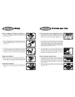
Place the stand on a stable and level work surface (figure 1).
Unpacking Components
Head and Reflected Illuminator Assembly
3.
Remove the head from the stand by loosening the reflected illuminator set
screw (figure 2) using the included 2mm hex wrench.
Grasp the head
firmly before loosening the set screw to prevent it from falling.
Set
the head aside.
Figure 1
Figure 2
Figure 3
Figure 4
Figure 5
4.
Remove the translucent packing cap from the bottom of the reflected
illuminator. Loosen the head set screw (figure 3) and remove the black
packing cap from the top of the illuminator. These can be set aside with the
packaging as they will not be needed.
5.
Insert the dovetail flange located on the bottom of the reflected illuminator
into the top of the stand with the black side facing down (figure 4). The end
of the illuminator with the round opening should be facing towards the rear
of the stand. Use the 2mm hex wrench to tighten the illuminator set screw
firmly.
6.
Insert the dovetail flange on the lamp housing into the hole located on the
rear of the reflected illuminator. Hold in place while tightening the lamp
housing set screw (figure 5) with the 2mm hex wrench.
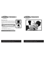
set screw
filter holder
filter wheel
polarizer
analyzer
polarizer
rotation wheel
set
screw
set
screw
packing
cap
packing
cap


