background image

11

104401

OWNER’S MANUAL

Pressure Testing Gas Supply
Piping System

Test Pressures In Excess Of 1/2 PSIG
(3.5 kPa)

1.

Disconnect appliance with its appliance
main gas valve (control valve) and equip-
ment shutoff valve from gas supply pip-
ing system. Pressures in excess of 1/2 psig
will damage heater regulator.

2.

Cap off open end of gas pipe where
equipment shutoff valve was connected.

3.

Pressurize supply piping system by ei-
ther using compressed air or opening
propane/LP supply tank valve.

4.

Check all joints of gas supply piping
system. Apply mixture of liquid soap
and water to gas joints. Bubbles form-
ing show a leak.

5.

Correct all leaks at once.

6.

Reconnect heater and equipment
shutoff valve to gas supply. Check re-
connected fittings for leaks.

Continued

 WARNING: Test all gas pip-

ing and connections for leaks
after installing or servicing. Cor-
rect all leaks at once.

 WARNING: Never use an open

flame to check for a leak. Apply a
mixture of liquid soap and water
to all joints. Bubbles forming show
a leak. Correct all leaks at once.

 CAUTION: Make sure exter-

nal regulator has been installed
between propane/LP supply and
heater. See guidelines under 

Con-

necting to Gas Supply, page 10.

INSTALLATION

Continued

CHECKING GAS
CONNECTIONS

Test Pressures Equal To or Less Than 1/
2 PSIG (3.5 kPa)

1.

Close equipment shutoff valve (see Fig-
ure 15).

2.

Pressurize supply piping system by ei-
ther using compressed air or opening
propane/LP supply tank valve.

3.

Check all joints from propane/LP sup-
ply tank to equipment shutoff valve (see
Figure 16). Apply mixture of liquid
soap and water to gas joints. Bubbles
forming show a leak.

4.

Correct all leaks at once.

Pressure Testing Heater Gas
Connections

1.

Open equipment shutoff valve (see Fig-
ure 15).

2.

Open propane/LP supply tank valve.

3.

Make sure control knob of heater is in
the OFF position.

4.

Check all joints from equipment shutoff
valve to thermostat gas valve (see Fig-
ure 16). Apply mixture of liquid soap
and water to gas joints. Bubbles form-
ing show a leak.

5.

Correct all leaks at once.

6.

Light heater (see Operating Heater,
pages 11 and 12). Check all other in-
ternal joints for leaks.

7.

Turn off heater (see To Turn Off Gas to
Appliance
, page 12).

8.

Replace front panel.

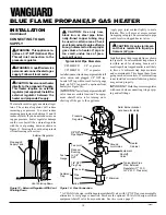
Figure 16 - Checking Gas Joints

Figure 15 - Equipment Shutoff Valve

Equipment
Shutoff
Valve

Propane/LP
Supply
Tank

Thermostat Gas Valve

OPERATING
HEATER

FOR YOUR SAFETY

READ BEFORE

LIGHTING

A. This appliance has a pilot which must

be lighted by hand. When lighting the
pilot, follow these instructions exactly.

B. BEFORE LIGHTING smell all

around the appliance area for gas. Be
sure to smell next to the floor because
some gas is heavier than air and will
settle on the floor.

WHAT TO DO IF YOU SMELL GAS
• Do not try to light any appliance.
• Do not touch any electric switch; do

not use any phone in your building.

• Immediately call your gas supplier

from a neighbor’s phone. Follow
the gas supplier’s instructions.

• If you cannot reach your gas sup-

plier, call the fire department.

C. Use only your hand to push in or turn

the gas control knob. Never use tools.
If the knob will not push in or turn
by hand, don’t try to repair it, call a
qualified service technician or gas
supplier. Force or attempted repair
may result in a fire or explosion.

D. Do not use this appliance if any part

has been under water. Immediately
call a qualified service technician to
inspect the appliance and to replace
any part of the control system and
any gas control which has been un-
der water.

 WARNING: If you do not fol-

low these instructions exactly, a
fire or explosion may result caus-
ing property damage, personal
injury or loss of life.

ON

POSIT

O

POS

Open

Closed

Equipment
Shutoff
Valve

Summary of Contents for VP2000BTD

Page 1: ...lier WARNING Improper installation adjustment alteration service or maintenance can cause injury or property damage Refer to this manualforcorrectinstallationand operational procedures For as sistance or additional information consult a qualified installer ser vice agency or the gas supplier WARNING This is an unvented gas fired heater It uses air oxy gen from the room in which it is installed Pro...

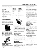
Page 2: ...er call the fire department 4 This heater shall not be installed in a bedroom or bathroom 5 This heater needs fresh outside air ven tilation to run properly This heater has an Oxygen Depletion Sensing ODS safety shutoff system The ODS shuts down the heater if not enough fresh air is available See Air for Combustion and Ventilation pages 4 through 6 6 Keep all air openings in front and bot tom of h...

Page 3: ... heater has a pilot with an Oxygen Depletion Sensing ODS safety shutoff system The ODS pilot is a required feature for vent free room heaters The ODS pilot shuts off the heater if there is not enough fresh air PIEZO IGNITION SYSTEM This heater has a piezo ignitor This system requires no matches batteries or other sources to light heater THERMOSTATIC HEAT CONTROL This heater has a thermostat sensin...

Page 4: ...n and ventilation However in buildings of unusually tight construction you must provide additional fresh air Unusually tight construction is de fined as construction where a walls and ceilings exposed to the outside atmosphere have a con tinuous water vapor retarder with a rating of one perm 6x10 11 kg per pa sec m2 or less with open ings gasketed or sealed and b weather stripping has been added o...

Page 5: ...t include direct vent gas appliances Direct vent draws combustion air from the outdoors and vents to the outdoors 4 Compare the maximum Btu Hr the space can support with the actual amount of Btu Hr used _________________ Btu Hr maximum the space can support _________________ Btu Hr actual amount of Btu Hr used Example 51 200 Btu Hr maximum the space can support 60 000 Btu Hr actual amount of Btu H...

Page 6: ...heatticwillactivatethepowervent AIR FOR COMBUSTION AND VENTILATION Continued Or Remove Door into Adjoining Room Option 3 Ventilation Grills Into Adjoining Room Option 2 12 12 Ventilation Grills into Adjoining Room Option 1 VENTILATION AIR Ventilation Air From Inside Building Thisfreshairwouldcomefromanadjoining unconfined space When ventilating to an adjoining unconfined space you must pro vide tw...

Page 7: ...r kerosene lamps etc in the air exist may discolor walls WARNING Never install the heater in a bedroom or bathroom in a recreational vehicle where curtains furniture clothing or other flammable objects are less than 36 inches from the front top or sides of the heater as a fireplace insert in high traffic areas in windy or drafty areas You can locate heater on floor away from a wall An optional flo...

Page 8: ...thod pro vides the strongest hold Insert mounting screws through mounting bracket and into wall studs Attaching to Wall Anchor This method allows you to attach mounting bracket to hollow walls wall areas between studs or to solid walls concrete or masonry Decidewhichmethodbettersuitsyourneeds Eithermethodwillprovideasecureholdfor the mounting bracket INSTALLATION Continued Figure 5 Attaching Therm...

Page 9: ...g screws through bracket and into wall anchors 7 Tighten screws until mounting bracket is firmly fastened to wall Placing Heater On Mounting Bracket 1 Locate two horizontal slots on back panel of heater 2 Place heater onto mounting bracket Slide horizontal slots onto stand out tabs on mounting bracket Figure 10 Popping Open Anchor Wings For Thin Walls Figure 11 Mounting Heater Onto Mount ing Brack...

Page 10: ...off valve is for turning on or shutting off the gas to the appliance CAUTION Use only new black iron or steel pipe Inter nally tinned copper tubing may be used in certain areas Check yourlocalcodes Usepipeoflarge enough diameter to allow proper gas volume to heater If pipe is too small undue loss of pres sure will occur Installsedimenttrapinsupplylineasshown in Figure 14 Locate sediment trap where...

Page 11: ...Open propane LP supply tank valve 3 Make sure control knob of heater is in the OFF position 4 Check all joints from equipment shutoff valve to thermostat gas valve see Fig ure 16 Apply mixture of liquid soap and water to gas joints Bubbles form ing show a leak 5 Correct all leaks at once 6 Light heater see Operating Heater pages 11 and 12 Check all other in ternal joints for leaks 7 Turn off heate...

Page 12: ... for repairs Untilrepairsaremade lightpilotwith match To light pilot with match see Manual Lighting Procedure 7 Keep control knob pressed in for 30 seconds after lighting pilot After 30 seconds release control knob Ifcontrolknobdoesnotpopupwhen released contact a qualified service person or gas supplier for repairs Note If pilot goes out repeat steps 3through7 Thisheaterhasasafety interlock system...

Page 13: ... HOLE We recommend that you clean the unit every 2 500hoursofoperationoreverythreemonths Wealsorecommendthatyoukeeptheburner tubeandpilotassemblycleanandfreeofdust and dirt To clean these parts we recommend using compressed air no greater than 30 PSI Yourlocalcomputerstore hardwarestore or home center may carry compressed air in a can You can use a vacuum cleaner in the blow position If using comp...

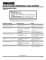
Page 14: ...ed 8 Control valve damaged REMEDY 1 Replace ignitor 2 Replace ignitor 3 Reconnect ignitor cable 4 Free ignitor cable if pinched by any metal or tubing Keep ignitor cable dry 5 Replace ignitor cable 6 Replace piezo ignitor 1 Turn on gas supply or open equipment shutoff valve 2 Turn control knob to PILOT position 3 Press in control knob while in PILOT position 4 Continue holding down control knob Re...

Page 15: ...Maintenance page 13 2 Replace gas regulator 1 Problem will stop after a few hours of operation 1 Turn control knob to LO position and let warm up for a minute 2 Operate burner until air is removed from line Have gas line checked by local pro pane LP gas company 3 Observe minimum installation clear ances see Figure 4 page 7 4 Clean burner see Cleaning and Mainte nance page 13 or replace burner orif...

Page 16: ...oise just after burner is lit or shut off Heater produces unwanted odors Heater shuts off in use ODS operates Gas odor even when control knob is in OFF position Gas odor during combustion Moisture condensationnoticedonwindows REMEDY 1 This is common with most heaters If noise is excessive contact qualified ser vice person 1 Ventilate room Stop using odor caus ing products while heater is running 2...

Page 17: ...placed under warranty PARTS UNDER WARRANTY Contact authorized dealers of this product If they can t supply original replacement part s call DESA International s Techni cal Service Department at 1 800 323 5190 WhencallingDESAInternational haveready your name your address model and serial numbers of your heater how heater was malfunctioning typeofgasused propane LPornaturalgas purchase date Usually ...

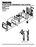
Page 18: ...18 104401 BLUE FLAME PROPANE LP GAS HEATER ODS Pilot Assembly 12 1 ILLUSTRATED PARTS BREAKDOWN VP2000BTD VP2800BTD 12 2 1 2 3 4 5 6 8 9 10 10 11 12 13 14 15 17 19 20 21 22 23 16 24 7 18 ...

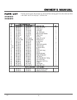
Page 19: ...ctor Unit 1 10 098271 03 098271 03 Ignitor Cable 1 11 098249 01 098249 01 Nut M5 2 12 103594 04 103594 04 ODS Pilot Assembly 1 12 1 098514 01 098514 01 Thermocouple 1 12 2 106842 01 106842 01 Ignitor Electrode 1 13 103446 01 103447 01 Burner 1 14 099387 03 099387 03 3 16 Pilot Tubing 1 15 103845 05 103845 07 Injector 1 16 099066 01 099066 01 Mounting Bracket 1 17 099415 06 099415 06 Pressure Regul...

Page 20: ...The heater MUST be installed by a qualified installer in accordance with all local codes and instructions furnished with the unit This warranty does not apply to parts that are not in original condition because of normal wear and tear or parts that fail or become damaged as a result of misuse accidents lack of proper maintenance or defects caused by improper installation Travel diagnostic cost lab...

Reviews: