background image

VANNER INCORPORATED


20-1050CUL INVERTER/CHARGER—OWNER'S MANUAL


13 


Limited Warranty


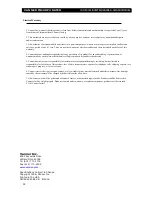
1. Vanner Inc., warrants that this product is free from defects in materials and workmanship for a period of one (1) year 
from its date of shipment from Vanner's factory. 
 
2. This warranty does not cover defects caused by misuse, neglect, accident, reversed polarity, unauthorized repairs, 
and/or replacements. 
 
3. All warranties of merchantability and fitness for a particular purpose; written or oral, express or implied, shall extend 
only for a period of one (1) year. There are no other warranties which extend beyond those described on the face of this 
warranty. 
 
4. Vanner does not undertake responsibility to any purchaser of its product for any undertaking, representation, or 
warranty made by any dealers or distributors selling its products beyond herein expressed. 
 
5. Vanner does not assume responsibility for incidental or consequential damages, including, but not limited to 
responsibility for loss of use of this product, loss of time, inconvenience, expense for telephone calls, shipping expense, loss 
or damage to property, or loss of revenue. 
 
6. Vanner reserves the right to repair, replace, or allow credit for any material returned under this warranty. Any damage 
caused by the customer will be charged or deducted from the allowance. 
 
7. All warranty work will be performed at Vanner's factory, or authorized repair facility. Products shall be delivered to 
Vanner's facility, freight prepaid. Products repaired under warranty, or replacement parts or  products will be returned, 
F.O.B. Vanner factory. 


Vanner Inc. 

4282 Reynolds Drive 
Hilliard, Ohio 43026 

Tel (614) 771-2718 
Fax (614) 771-4904 

www.vanner.com


Specifications Subject to Change 
Copyright 1996, Vanner Inc. 
Printed in the USA 

OM/A96283 REV B   8/2016


Summary of Contents for 20-1050CUL

Page 1: ......

Page 2: ...e Panel Operation 9 Section 6 Operating the 20 1050CUL Inverter Charger 10 Section 7 Troubleshooting 11 Section 8 GFCI Test Record 12 Warranty 13 List of Figures Figure 1 System Diagram 2 Figure 2 Federal Specification KKK A 1822D Diagram 7 Figure 3 1FM I Module Remote Wiring 8 Icon Legend Note Warning VANNER INC 4282 Reynolds Drive Hilliard Ohio 43026 800 AC POWER Tel 614 771 2718 Fax 614 771 490...

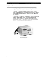
Page 3: ...mance and reliability for your emergency vehicle With minimum maintenance and care you can expect years of trouble free service from your Vanner product The 20 1050CUL is a 12 VDC to 120 VAC inverter with a built in battery charger conditioner and transfer relay This unit is equipped with an AC line cord for connecting AC input power shore utility power and a receptacle with a Ground Fault Circuit...

Page 4: ...cally charge batteries maintaining the battery s integrity and reducing the likelihood of premature failure High Charge Mode While in the High Charge mode the unit continuously charges at a constant current of 55 Amps high setting for large battery banks or 15 0 Amps low setting for small battery banks such as two group 31 batteries The unit will charge until the battery cells reach 14 2 VDC for f...

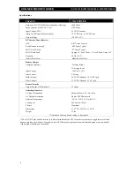
Page 5: ...Current Draw Battery OFF 0 017 Amps Typical Load Demand waiting 0 09 Amps Typical Full ON at No Load 0 7 Amps Typical Full ON with Load Approx AC Load Watts 10 or AC Load Amps x 12 Frequency 60 Hz 0 1 Output Wave Form Modified Sine Wave Battery Charger Charging Capacity 55 Amps High 15 0 Amps Low Input Voltage 120 VAC 10 Input Current 8 0 Amps Bulk Voltage 14 2 VDC flooded 14 1 VDC gel Float Volta...

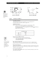
Page 6: ...at the ON OFF RESET Inverter Switch is in the OFF RESET position The button should NOT be pushed in DC Cable Lengt h Size Maximum 2AW G 12ft 1 0AWG 20ft Step 2 Select a location for the unit An ideal installation location has the following characteristics Close to the battery within six feet using 2 AWG wire Protected from the weather Protected from the weather Step 3 Route DC input cables Route t...

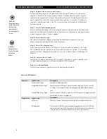
Page 7: ... Step 9 Select the charging rate In the high position the charge is 55 Amps In the low position the output is 15 0 Amps We recommend the low position as the best selection when two group 31 or smaller batteries are used Charging at too high of a rate for a given battery will damage the batteries Step 10 Connect the AC loads Connect the AC loads to the inverter GFCI receptacle Any time AC power is ...

Page 8: ...e near full charge and the charger is in the maintenance mode In this mode the charger is holding the batteries at the float voltage The charging current is limited based on the position of the Charger High Low switch Section 3 Installing the IFM1 Interface Module This section describes the installation of the optional Vanner Model IFM 1 Interface Module Refer to the information provided in the IF...

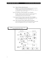
Page 9: ... Pins 2 through 5 Red to Pin 2 Black to Pin 3 Green to Pins 4 and 5 If no remote switch is used two jumpers must be installed The first jumper connects Pin 2 to Pin 3 the second jumper connects Pin 4 to Pin 5 See Figure 3 Step 5 Connect the Inverter Remote Status Display Panel Optional Connect the gray green and red wires from the inverter panel through the OEM harness to the IFM1 Module Pins 6 gr...

Page 10: ...r easy installation The following installation procedure applies to both the inverter and charger panels Step 1 Select a location for the panel Identify the desired location for the inverter and charger panels Step 2 Identify wires for installation Identify the gray green and red wires on the inverter panel and vehicle s electrical system Identify the brown white and black wires on the charger pan...

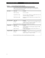
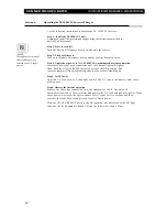
Page 11: ...is on in the Load Demand mode and is waiting for AC load to be turned ON Inverter Fault LED Light Action Description Red Light Unit shutdown Check the inverter s front panel LEDs for reason of shutdown Low Battery Overload or Overtemp Refer to the Troubleshooting section of this manual for fault diagnostic information Charger LED Light Action Description Blinking Green Light AC shore utility power...

Page 12: ...l light or flash Push the ON OFF RESET Inverter Switch to the ON position The inverter lamp will flash indicating that the inverter is standing by Step 5 Verify Power Apply an AC load such as a shop light or drill The AC load is run directly from shore utility power Step 6 Observe the inverter operation Remove the shore line connection from the emergency vehicle The unit will automatically switch ...

Page 13: ...TOM ON lamp fully illuminates AC load does not run SOLUTION Check and reset circuit breaker and GFCI receptacle Verify AC load and cord are in proper condition SYMPTOM BATTERY LOW lamp illuminates when AC load is applied SOLUTION Check battery connections Check battery condition Recharge battery if voltage is less than 10 5 VDC Check the vehicle s alternator charging system for proper operation SY...

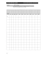
Page 14: ...WNER SMANUAL 12 Section 8 GFCI Test Record For maximum protection against electrical shock hazard operate the Test Switch on the Ground Fault Circuit Interrupter at least once a month ENTER YEAR JAN FEB MAR APR MAY JUNE JULY AUG SEPT OCT NOV DEC 20_ ...

Page 15: ...tributors selling its products beyond herein expressed 5 Vanner does not assume responsibility for incidental or consequential damages including but not limited to responsibility for loss of use of this product loss of time inconvenience expense for telephone calls shipping expense loss or damage to property or loss of revenue 6 Vanner reserves the right to repair replace or allow credit for any m...

Reviews: