VANNER INCORPORATED
20-1050CUL INVERTER/CHARGER—OWNER'S MANUAL
5
WARNING
Improper Battery
Type Switch setting
may damage
batteries.
WARNING
Battery input cables
must be connected to
the battery with
proper polarity to
avoid damaging the
inverter.
Step 6: Connect the inverter to the battery.
Connect the black, negative DC input cable from the quick connector to the battery
negative (-) terminal. This battery negative terminal is usually where the battery negative
connects to the engine block or frame. Connect the red, positive DC input cable from the
quick connector to the in/line fuse near the battery positive (+) terminal. This battery
terminal is usually connected to the DC electrical system at the load side of the Battery
disconnect Switch.
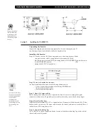
Step 7: Select Load Demand option.
Select Load Demand option if desired, using the proper switch position on the front panel
Setup Switch. With Load demand ON, the inverter conserves battery energy and operates only
when a load greater than 5 Watts is applied.
Step 8: Select battery type.
The charger is capable of charging both gel and flooded lead acid batteries. Select the
battery type using the Setup Switch on the front panel.
Step 9: Select the charging rate.
In the high position the charge is 55 Amps. In the low position the output is 15.0 Amps.
We recommend the low position as the best selection when two (group 31 or smaller)
batteries are used. Charging at too high of a rate for a given battery will damage the
batteries.
Step 10: Connect the AC loads.
Connect the AC loads to the inverter GFCI receptacle. Any time AC power is applied to the
AC input (shore/utility power), it will pass through this GFCI receptacle.
Step 11: Verify installation.
Verify all connections are tight and secure for maximum performance.
Inverter LED Displays
Inverter
Light Action
Description
Steady Green Light .
Inverter is On and operating
Single Blink Green Light
Inverter circuit is Off. Shore power is On and supplying AC power to the
AC loads. The inverter will turn On and supply the load if shore power is
lost.
Double Blink Green Light
Inverter circuit is Off. Shore power is Off. The inverter is waiting for a load
greater than 5 watts to be turned on.
Battery Low
Light Action
Description
Solid red
Inverter is On and the battery is almost too low to operate the inverter.
Blinking Red
The inverter is Off. The battery voltage dropped below 10.5 volts DC and
the inverter shut itself Off. Once shut off, the batteries must be recharged.
Then, the inverter On/Off switch must be cycled to reset the unit.
Summary of Contents for 20-1050CUL
Page 1: ......

