background image

Page 

3

 of 

12


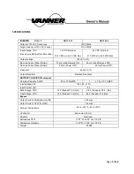
SPECIFICATIONS 


INVERTER 

Model #


QBC10-12


QBC10-24


Output at 120 VAC-Continuous


1050 Watts


Surge Capacity at 120 VAC (3 secs)


2100 Watts


Input Voltage, VDC 

(Deep Cycle Battery Recommended)


12 VDC, Nominal, 


10.5 VDC min.,16.0 VDC Max.


24 VDC, Nominal, 


21.0 VDC min.,32.0 VDC Max.


Output Voltage


120 VAC ± 5% 

...


No Load Current Draw (Battery)


75 ma (Load Demand ON)


55 ma (Load Demand ON)


No Load Current Draw (Battery)


20 ma (Power OFF)


25 ma (Power OFF)


Frequency 

_


60Hz ± 0.1%


Output Waveform


Modified Sine Wave


BATTERY CHARGER (if equipped)


Charging Capacity, AMPS


55 or 27.5 AMPS


27.5 or 13.7 AMPS


Input voltage, VAC


120 VAC ± 10%


Input Current, IAC


8.0


Bulk Voltage, VDC


14.2 (flooded) 14.1 (Gel)


28.4 (flooded) 28.2 (Gel )


Float Voltage, VDC


13.2 (flooded) 13.6 (Gel)


26.4 (flooded) 27.2 (Gel)


Bypass


Output Current, hardwired (H suffix)


30 amps


Output Current, GFCI (G suffix)


12 amps


Ambient Temperature


-40 to +105°F, -40 to +40°C 


Cooling Air


Fan-cooled, 30 cfm


Chassis


Aluminum


Dimensions GFCI


11.57" W x 5.94" H x 11.04" D


Dimensions Hardwire


11.57" W x 5.94" H x 13.04" D


Weight


22 LBS


Summary of Contents for BRAVO 1050

Page 1: ...Contents Introduction 2 General Description 2 Specifications 3 Installation Hardwire Units 4 Operation Hardwire Units 5 6 Installation GFCI Receptacle Units 7 Operation GFCI Receptacle Units 8 9 Troub...

Page 2: ...delay to ensure that full power is available the load is switched back to AC input power and the battery charger activates automatically to recharge the battery Inverter The Bravo QBC10 converts the p...

Page 3: ...F 25 ma Power OFF Frequency _ 60Hz 0 1 Output Waveform Modified Sine Wave BATTERY CHARGER if equipped Charging Capacity AMPS 55 or 27 5 AMPS 1 27 5 or 13 7 AMPS Input voltage VAC 120 VAC 10 Input Curr...

Page 4: ...the negative BLACK DC input cable to the battery negative terminal Connect the positive RED DC input cable to the battery positive terminal 6 Select the proper battery type GEL or flooded lead acid lo...

Page 5: ...ition If utility power is present the ON lamp will FLASH The FLASH indicates the inverter is standing by 4 If utility power is removed or lost and the ON OFF RESET Inverter Switch is in the ON positio...

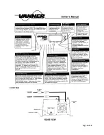
Page 6: ...Page 6 of 12 BACK PANEL...

Page 7: ...input cables from the inverter charger to the battery If required protect cables where they come into contact with hard or sharp edges 4 Install an inline fuse Bussman ANN 125 for 12 volt application...

Page 8: ...h to the ON position If utility power is present the ON lamp will FLASH The FLASH indicates the inverter is standing by 4 If utility power is removed or lost and the ON OFF RESET Inverter Switch is in...

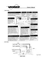
Page 9: ...Page 9 of 12 FRONT PANEL BACK PANEL...

Page 10: ...ow to the cooling fan or from ventilation holes Verify AC load is within unit s rated capacity OVERLOAD lamp lights when AC load is applied Verify AC load is within unit s rated capacity Try smaller A...

Page 11: ...harging is in progress and the green when the inverter is on or in load demand GFCI TEST RECORD For maximum protection against electrical shock hazard operate test switch on Ground Fault Circuit Inter...

Page 12: ...mplied warranty lasts so the above limitations may not apply to you Vanner does not undertake responsibility to any purchaser of its product for any undertaking representation or warranty made by any...

Reviews: