Installation and Start-up
IT SERIES Industrial True Sine Wave Inverter Owners Manual
21
7. Proper DC cable size is critical for the performance and safe operation of the inverter system.
The
DC Cable and Fuse Sizing Chart
shows the minimum recommended cable sizes. These sizes allow
a ½ volt maximum voltage drop at maximum inverter capacity and will insure optimum inverter
performance. Quick DC cable connectors are available. See Parts and Accessories.
8. Do not use the vehicle chassis as the DC negative conductor. The negative cable should be the same
size as the DC positive cable and should be connected directly to the battery negative terminal.
9. DC cables should be as short as possible.
Figure 10 DC Cable and Fuse Sizing Chart
Model Number
IT
12
-1400
IT
12
-1600
IT
12
-1800
IT
12
-2000
IT
12
-2200
S
IT
12
-2400
IT
12
-2600
IT
12
-2800
IT
12
-3000
IT
12
-3200
IT
12
-3600
P
L
IT
24
-3500
Cable Size
Distance from battery to inverter in feet
(Length of cable needed is 2 times the distance.)
1/0
12
11
10
9
NR
NR
NR
NR
NR
NR
NR
NR
2/0
16
13
12
11
NR
NR
NR
NR
NR
NR
NR
NR
3/0
20
16
15
14
14
NR
NR
NR
NR
NR
NR
NR
4/0
20
20
19
18
17
15
14
13
12
11*
10*
11
250MCM
20
20
20
20
20
17
16
16
14
13*
12*
13
Fuse (Bussmann)
Vanner part number
ANN300
04521
ANN400
04523
ANL500
03646
Fuse Holder
Vanner part number 03637 (Bussmann 4164)
*For 12 volt models rated-2800 watts and higher use cable rated 90°C, UL listed 4/0 cable 03558, or equal.
Note: A 500 amp fuse is required to achieve
full surge output capacity
on Model IT24-3500. Usage of the
500 amp fuse dictates using 4/0 cable or larger.
DC Wiring Installation Procedure
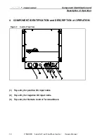
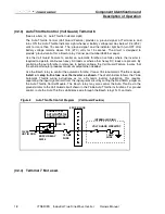
1. The DC wiring enclosure is located on the left front of the inverter. The DC cables may enter the
inverter through top, bottom or left side openings (see figures 1,2,and 3). Two cable clamps and four
plastic hole plugs are provided. Bolts are provided for connecting 5/16 diameter ring terminals to the
DC Input Contacts. Optional compression lugs (Vanner part no. D08241) are available for cables
sizes up to 250 MCM.
2. Select a location for the inverter. An ideal location is close to the battery; protected from weather and
moisture; and well ventilated.
3. Select an accessible location for the DC Fuse. The location should be within 18” of the battery and
accessible for visual inspection and replacement. If possible locate so the last DC connection can
safely be made at the fuse.

