VANNER
Incorporated
Owner’s Manual
LifeSine LSC12-1100 Owner’s Manual - 22 -
SECTION 9: INSTALLATION AND FUNCTION OF THE LSCR AND
LSIR Remote Status Display Panels.
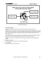
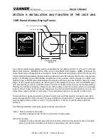
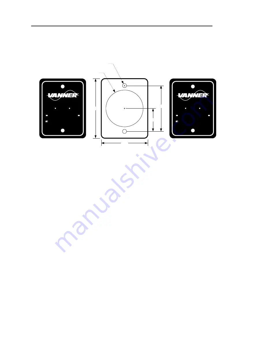
Two optional remote status display panels are available for the LifeSine LSC12-1100. One is for Charger
Status (Part Number –
LSCR
) and the other is for Inverter Status (Part Number –
LSIR
). (These are the
same remote status display panels used with the Vanner LifeStar inverter/charger.) Both the Charger and
Inverter Remote Status Display Panels contain a green and a red LED indicator light. On the charger status
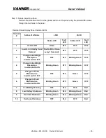
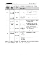
panel, a FLASHING green LED indicates the presence of shore power and the charger is in Bulk or Ab-
sorption Stage. A SOLID green LED indicates the presence of shore power and that the charger is in Float
stage. On the inverter status panel, the SOLID green LED indicates the unit is ON. A FLASHING green
LED indicates the inverter is in Standby mode. (“Inverter in standby mode” is when the inverter switch is
ON while the LifeSine is in Battery Charger mode. If shore power is lost, the inverter will turn on and supply
power to the AC loads.) For both the remotes panels, the red Fault LED indicates problems such as over
temperature, output overload, or low battery. The remote status panels do not provide remote control.
The panels have a gasket seal which will keep the electronics safe from weather and water spray. Each
panel is equipped with a RJ45 connector for easy installation and replacement. The panels are available
without cables (LSCR or LSIR), or with a 13’ cable (LSCR-13, LSIR-13) or with 25’ cable (LSCR-25,
LSIR-25).
The following installation procedure applies to remote status panels.
Step 1: Select a location for the panel.
Identify the desired location for the inverter and/or charger panels.
Step 2: Route cable.
Carefully route the modular cable from the front of the LifeSine to the remote location. This cable
does not need to be shielded but it should be routed away from the AC cables.
POWER INVERTER
Fault
Standby
ON
Fault
AC ON/
High Charge
AC ON/
Maint. Charge
CHARGE INDICATOR
2.22
1.11
Remote Mounting
Pattern
Fault
Ø 0.110 (#35 Drill Bit) Hole (2 PLCS)
Ø 1.875 (1 7/8) Hole
2.360
3.015

