background image

VANNER

 Incorporated


                                                 Owner’s Manual


LifeSine  LSC12-1100      Owner’s Manual                                                               - 3 - 


Table of Contents 


Section 1: General Installation Diagram

 ............................................................................................ 2 

Section 2: Introduction

 ........................................................................................................................... 4 

Section 3: Specifications

 ....................................................................................................................... 5 

Section 4: Functionality

 ......................................................................................................................... 6 

Section 5: Physical Dimensions

 ........................................................................................................ 10 

Section 6: Front and Rear Panel Component

 ................................................................................. 11 

Section 7: IMPORTANT SAFETY INSTRUCTIONS

 ......................................................................... 16 

Section 8: Installing the LifeSine LSC12-1100

 ............................................................................... 18 

Section 9: Installation and function of the LSCR and

 .................................................................. 22 

Section 10: Operating the LifeSine12-1100

 ..................................................................................... 24 

Section 11: Fault Shutdown Conditions and Solutions

 ............................................................... 25 

Section 12: Troubleshooting the LifeSine LSC12-1100

 ............................................................... 26 


Summary of Contents for LifeSine LSC12-1100

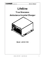
Page 1: ...VANNERIncorporated Owner s Manual LifeSine LSC12 1100 Owner s Manual 1 LifeSine True Sinewave Ambulance Inverter Charger Model LSC12 1100...

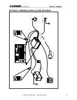
Page 2: ...VANNERIncorporated Owner s Manual LifeSine LSC12 1100 Owner s Manual 2 SECTION 1 GENERAL INSTALLATION DIAGRAM V B A T T LO A D S TA T U S CH A R G ER...

Page 3: ...Functionality 6 Section 5 Physical Dimensions 10 Section 6 Front and Rear Panel Component 11 Section 7 IMPORTANT SAFETY INSTRUCTIONS 16 Section 8 Installing the LifeSine LSC12 1100 18 Section 9 Insta...

Page 4: ...ur Vanner product The LSC12 1100 is a 12 VDC to 120 VAC true sine wave inverter with built in battery charger transfer relay and KKK Spec 12VDC Portable Equipment Charging Circuit The unit is equipped...

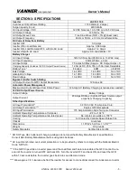
Page 5: ...Drawn from Shore Power 12 Amps AC Battery Charging is reduced as needed 12V DC Output Power Source Output Voltage Battery Voltage Output Current 20 Amps DC Max Subtract Power Source output amps from C...

Page 6: ...stallation Step 9 Remote Control Load Demand The Load Demand feature is not recommended for vehicle applications The recommended Load Demand setting for ambulance is OFF DIP Switch 7 OFF DOWN In vehic...

Page 7: ...is Flooded Note After making a change to the Setup DIP Switch settings shore power must be removed and the inverter must be cycled OFF ON for the change to go into effect The LifeSine LSC12 1100 must...

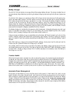
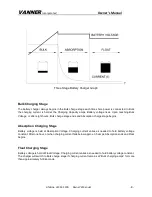
Page 8: ...k charge stage ends and Absorption charge stage begins Absorption Charging Stage Battery voltage is held at Absorption Voltage Charging current varies as needed to hold battery voltage constant After...

Page 9: ...rtable devices when the vehicle is either running or the optional battery conditioner is connected to shore power Circuit protection shall be provided and shall have a minimum 10 amp capacity An addit...

Page 10: ...VANNERIncorporated Owner s Manual LifeSine LSC12 1100 Owner s Manual 10 SECTION 5 PHYSICAL DIMENSIONS 2 76 3 32 4 13 9 13 9 76 47 2x 283 2x 642 4x 374 2x 283 5 9 11 4 11 6 10 63 10 6...

Page 11: ...32V E104586 LISTED 5DA7 L O A D S T A T U S C H A R G E R N O COM N C ENB ENB GND Experience Power Experience Vanner INV CHG A B P N M K J L C D E F G H LSC12 1100 Front Panel Components A AC Input Co...

Page 12: ...rt ing the wire straight into bottom opening Release wire by pressing the grooved button above the opening Terminal Description 1 Alarm Dry Contact Normally Open 2 Alarm Dry Contact Common 3 Alarm Dry...

Page 13: ...ery Over Voltage Shutdown Battery Voltage AC Load System Status and LSIR All three LED s blink ON for 0 5 second every 10 seconds The inverter is in Load Demand Mode Load Demand is not recommended for...

Page 14: ...tings select AC Output Frequency 60Hz Battery Charging Current 50Amps Battery Type Flooded Load Demand Feature OFF 12VDC Output Power Circuit ON Note After making any change to the Setup DIP Switch se...

Page 15: ...wner s Manual LifeSine LSC12 1100 Owner s Manual 15 Rear panel A B C LSC12 1100 View of back panel and intake fan A DC input connector 175 AMP Anderson Connecter B Chassis ground C Cooling Air Intake...

Page 16: ...e published by battery manufacturer and manufacturer of any unit you intend to use in vicinity of battery Review cautionary marking on these products and on engine 7 PERSONAL PRECAUTIONS AROUND BATTER...

Page 17: ...ithout cell caps carefully follow manufacturer s recharging instructions 8 UNIT LOCATION a Locate unit away from battery in a separate well ventilated compartment b Never install unit directly above b...

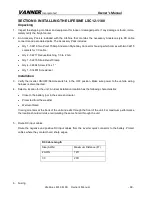
Page 18: ...p Qty 4 04864 Screw 14 x 1 Qty 1 014801 Screwdriver Installation 3 Verify the inverter ON OFF Remote switch is in the OFF position Make sure power to the vehicle wiring harness is disconnected 4 Selec...

Page 19: ...ar the bat tery positive terminal The positive DC cable must be connected to the DC electrical system on the battery side of the Battery Disconnect Switch so the charger can charge the battery while t...

Page 20: ...remote control by setting the ON OFF REMOTE Switch to the ON or to the OFF position Remote control switch arrangements for remote control of inverter Connect only one remote control signal to the Life...

Page 21: ...d accept two remote control signals The inverter treated two remote signals as if two switches were operat ing in series Both signals had to be ON for the inverter to turn ON If either signal turned O...

Page 22: ...hile the LifeSine is in Battery Charger mode If shore power is lost the inverter will turn on and supply power to the AC loads For both the remotes panels the red Fault LED indicates problems such as...

Page 23: ...erter in Standby Load Demand Double Blink Green every 10 seconds OFF OFF OFF 3 Charger in Bulk High Absorption Inverter switch OFF OFF OFF Blinking Green OFF 4 Charger in Bulk High Absorption Inverter...

Page 24: ...inverter is ON Step 5 Verify AC Output Power Apply an AC load such as a shop light or drill to the inverter s GFCI receptacle Verify opera tion Step 6 Apply shore power Turn vehicle OFF Apply shore po...

Page 25: ...enings are not obstructed 2 Reduce ambient temperature Orange Slow Blink N A AC Input Over Under Voltage Shutdown 1 Verify the AC input voltage is be tween 90Vac 132Vac Fast Blink N A AC Input Over Cu...

Page 26: ...W lamp illuminates when AC load is applied SOLUTION Check battery connections Check battery condition Recharge battery if voltage is less than 10 5 VDC Check the vehicle s alternator charging system f...

Page 27: ...VANNERIncorporated Owner s Manual LifeSine LSC12 1100 Owner s Manual 27 Notes...

Page 28: ...00 Owner s Manual 28 Vanner Incorporated 4282 Reynolds Drive Hilliard Ohio 43026 Toll free 1 800 AC POWER 1 800 227 6937 Tel 614 771 2718 Fax 614 771 4904 www vanner com e mail pwrsales vanner com Own...

Reviews: