VANNER
Incorporated
Owner’s Manual
LifeSine LSC12-1100 Owner’s Manual - 5 -
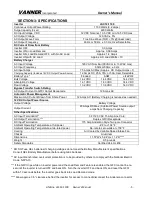
SECTION 3: SPECIFICATIONS
Inverter
LSC12-1100
Continuous Output Power Rating
1100 Watts (9.2 amps)
Surge Capacity (3 sec)
2200 Watts
DC Input Voltage, VDC
12 VDC Nominal, 10.5 VDC min,16.5 VDC max.
AC Output Voltage
120 VAC ± 5%
AC Output Wave Form
True Sine Wave (THD < 3% @ linear load)
AC Output Frequency
60 Hz or 50 Hz, ± 0.3 Hz, User Selectable
DC Current Draw from Battery
Inverter OFF
0.0 Amps
Inverter ON in Load Demand
Approx. 0.08 Amps
Inverter ON, Load Demand OFF, with No AC Load
Approx. 1.4 Amps
Inverter ON with AC Load
Approx. AC Load Watts ÷ 10
Battery Charger
AC Input Voltage
120 VAC Nominal (90VAC min, 132VAC max)
AC Input Frequency
60Hz or 50Hz, ± 3 Hz
AC Input Amps
7.5 Amps AC Max (Approx. DC Output Amps ÷ 7)
Charging Capacity (Includes 12V DC Output Power Source)
12 Amps DC, 25A, 37A, or 50A, User Selectable
Battery Type *
Flooded
AGM
LiFePO4
Bulk Voltage
14.2 VDC
14.4 VDC
14.4 VDC
Absorption Voltage
14.1 VDC
14.3 VDC
14.4 VDC
Float Voltage
13.2 VDC
13.6 VDC
14.0 VDC
Bypass Transfer Switch Rating
AC Output Current to GFCI Output Receptacle
12 Amps AC
Automatic Power Management
Maximum AC Current Drawn from Shore Power
12 Amps AC (Battery Charging is reduced as needed.)
12V DC Output Power Source
Output Voltage
Battery Voltage
Output Current
20 Amps DC Max. (Subtract Power Source output
amps from Charging Capacity)
Other Specifications
AC Input Termination**
3 Ft 120 VAC 15 Amp Line Cord
AC Output Termination ***
Duplex GFCI Receptacle
DC Input Termination
175 Amp Anderson Style Two-pole Connector
Ambient Operating Temperature at full power
-4°F to +104°F
Ambient Operating Temperature at de-rated power
De-rate to zero watts at +158°F
Cooling
Air Cooled by Variable Speed Intake Fan
Chassis
Aluminum
Dimensions
11.57”W x 5.94”H x 11.4”D****
Weight
9.5 pounds
Safety Standards
Certified UL/cUL 458
* DO NOT use GEL batteries if charging voltages do not meet the Battery Manufacturer’s specifications.
Consult GEL Battery Manufacturer before using GEL batteries.
** AC input branch rated overcurrent protection is to be provided by others to comply with the National Electric
Code, NFPA 70.
*** If the GFCI trips while on inverter power and the Load Demand Feature is enabled, the GFCI cannot be re-
set until the inverter is turned OFF and back ON. Turn the inverter OFF and back ON, and reset the GFCI
within 10 seconds before the inverter goes back into Load Demand mode.
**** Allow approx. 3.5” clearance behind the inverter for access to connect/disconnect the Anderson connector.

