Airplane Flight Manual
Van’s Aircraft RV-7A
HB-YMT
7 Aeroplane and system description – Page 12
Edition 01.11.2017
Switch Panel
A pilot accessible panel with a green master switch, red emergency
button, three two-position switches with LEDs, a light sensor, and knob
for controlling engine ignition (a MAG switch). Note that the magnetos
are wired directly to the MAG switch on the SP and are NOT controlled by
the VP-200 system.
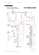
This aircraft uses the so called “Configuration 1”.
One Control Unit, a single battery and a single alternator make up the
backbone of the system. The Battery is a PC680 from Odyssey Batteries,
System Voltage 10.5-13 VDC. It is capable of sustaining a 5A load for over
2.5hrs. The Alternator is a 55A Nippon Denso automotive unit.
The system is designed to present modes for a typical flight, based on
which it can automatically control devices, present checklists and change
softkey behaviour.

