Airplane Flight Manual
HB-YMT
01/00 Description of the Airplane and its Systems
7–39
7.10.6
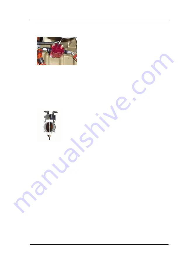
Fuel Flow Sensor
The fuel flow sensor is plumbed between the mechanical
fuel pump and the throttle body. It provides measurement of
actual fuel consumption by the engine.
7.10.7
Throttle Body
Air Throttle Body and Fuel Metering Unit Assembly:
The air throttle body contains the butterfly valve that controls
the flow of air to the engine as positioned by the cockpit
throttle control lever.
The fuel metering cam is attached to the throttle shaft so the
butterfly valve and the fuel metering cam move in unison.
There are two fuel lines attached to the fuel metering unit.
One line is un-metered fuel input to the fuel metering unit
and the second line is metered fuel output to the fuel
manifold valve.
Summary of Contents for HB-YMT
Page 19: ...Airplane Flight Manual HB YMT 01 00 General 1 13 1 6 Three View Drawing...
Page 42: ......
Page 53: ...Airplane Flight Manual HB YMT 01 00 Emergency Procedures 3 11...
Page 54: ......
Page 72: ......
Page 77: ...Airplane Flight Manual HB YMT 01 00 Performance 5 5 5 3 3 Takeoff Distance...
Page 78: ...HB YMT Airplane Flight Manual 5 6 Performance 01 00 5 3 4 Landing Distances...
Page 79: ...Airplane Flight Manual HB YMT 01 00 Performance 5 7 5 3 5 Climb Performance Takeoff Climb...
Page 80: ...HB YMT Airplane Flight Manual 5 8 Performance 01 00...
Page 81: ...Airplane Flight Manual HB YMT 01 00 Performance 5 9 5 3 6 Table for Setting Engine Performance...
Page 82: ...HB YMT Airplane Flight Manual 5 10 Performance 01 00 5 3 7 Pressure Altitude Density Altitude...
Page 83: ...Airplane Flight Manual HB YMT 01 00 Performance 5 11 5 3 8 Cruising True Airspeed TAS...
Page 86: ...HB YMT Airplane Flight Manual 5 14 Performance 01 00 5 3 10 Crosswind Performance...
Page 88: ......
Page 93: ...Airplane Flight Manual HB YMT 01 00 Mass and Balance 6 5 6 4 2 Basic Empty Mass and CG...
Page 176: ......


