SECTION 11:
ENGINE AND PROPELLER INSTALLATION
RV AIRCRAFT
11-29
sect 11r8 06/24/11
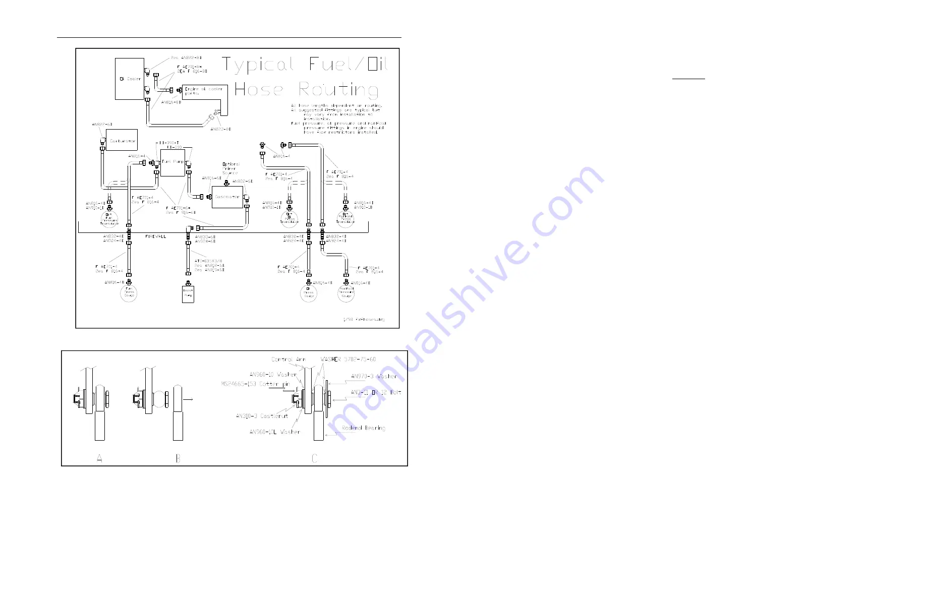
TYPICAL INSTALLATION OF A CONTROL CABLE TO THE MIXURE OR THROTTLE ARM
The rodend bearing (at the engine end of the throttle and mixture cables) and control arm (on the carburetor) are connected by an
AN bolt, sized as necessary, (an AN3 is shown in the example above) with a hole for the cotter pin. On each side of the rodend is a
small spacer washer (WASHER 5702-75-60) which holds the rodend away from the washer and the control arm, and allows the
bearing to move freely at various angles without binding. Examples A and B show a situation where the rodend bearing housing
has worn and slipped off the ball and bolt. This is prevented by installing the AN970-3 capture washer. The AN960-10 and
AN960-10L washers are used as needed to position the nut for the cotter pin. The AN310-3 castle nut should be torqued to 20-25
in-lbs. The MS24665-153 cotter pin restrains the nut from backing off.
NOTE: the hole in the mixture arm is typically 1/4” and
will need a bushing to fit an AN3 bolt.
TYPICAL ENGINE PLUMBING DIAGRAM
This should be taken as a guide only as it is likely your airplane will vary.
NOTES


