www.fmiproducts.com
125527-01A
19
iNStallatioN
Continued
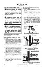
LBG(18,24,30)-SM MODELS
LBG36-SM MODELS
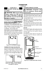
Figure 22 - Correct Log Placement
CONCRETE LOG MODELS
LBG(18,24,30)-RM
Each log is marked with a number. These
numbers will help you identify the log when
installing (see chart on page 20). It is very
important to install these logs exactly as
instructed. Do not modify logs. Only use logs
supplied with heater.
Note: Your appliance may vary from model
shown but log placement will be the same.
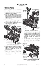
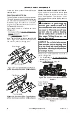
1. Place fiber ramp-log in center on chassis
as shown in Figure 23. The fiber ramp-log
can be identified by its shape and much
lighter weight when compared to the other
logs.
Figure 23 - Installing Log Set
Base Assembly
Ramp
Log
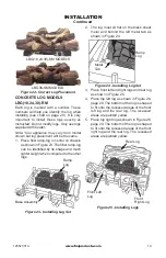
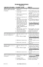
Figure 24 - Installing Log Set
Ramp
Log
Metal
Tab
2. The log must sit flat on the black sheet
metal and behind the left metal tab as
shown in Figure 24.
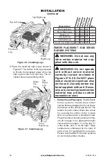
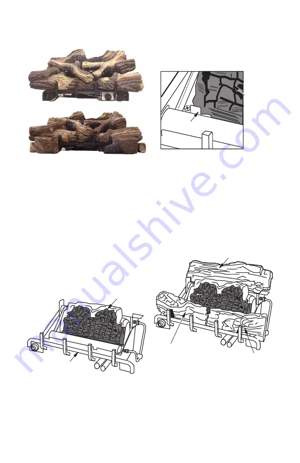
3. Place front left and right logs and rear log
as shown in Figure 25.
4. Place top left log as shown in Figure 26,
page 20. The bottom of the log is shaped
to fit onto the recessed areas of the front
left log and the rear log. The recessed
areas are painted yellow.
5. Place top right log as shown in Figure 26,
page 20. The bottom of the log is shaped
to fit onto the recessed areas of the front
right log and the rear log. The recessed
areas are painted yellow.
Rear Log
Front
Right Log
Front Left
Log
Figure 25 - Installing Logs


