background image

www.fmiproducts.com

125784-01D

4

SAFETY

Continued

1.  This appliance is only for use with the type 

of gas indicated on the rating plate. This 

appliance is not convertible for use with 

other gases.

2.  Do not place propane/LP supply tank(s) 

inside any structure. Locate propane/

LP supply tank(s) outdoors (propane/LP 

units only).

3.  If you smell gas

• shut off gas supply

• do not try to light any appliance

• do not touch any electrical switch; do not 

use any phone in your building

• immediately call your gas supplier from 

a neighbor’s phone. Follow the gas sup-

plier’s instructions

• if you cannot reach your gas supplier, 

call the fire department

4.  This heater shall not be installed in a bed-

room or bathroom.

5.  Before installing in a solid fuel burning fire

-

place, the chimney flue and firebox must 

be cleaned of soot, creosote, ashes and 

loose paint by a qualified chimney cleaner. 

Creosote will ignite if highly heated. A dirty 

chimney  flue  may  create  and  distribute 

soot within the house. Inspect chimney 

flue for damage. If damaged, repair flue 

and firebox before operating heater.

6.  Do not burn solid-fuel in a masonry or 

UL127  factory-built  fireplace  in  which  a 

vent-free room heater is installed.

7.  If fireplace has glass doors, never operate 

this heater with glass doors closed. If you 

operate  heater  with  doors  closed,  heat 

buildup inside fireplace will cause glass to 

burst. Make sure there are no obstructions 

across openings of fireplace.

8.  To prevent the creation of soot, follow the 

instructions in 

Cleaning and Maintenance

page 34.

9.  Before using furniture polish, wax, carpet 

cleaner or similar products, turn heater off. If 

heated, the vapors from these products may 

create a white powder residue within burner 

box or on adjacent walls and furniture.

10. This heater needs fresh, outside air ven

-

tilation to run properly. This heater has an 

Oxygen Depletion Sensing (ODS) safety 

shutoff system. The ODS shuts down the 

heater if enough fresh air is not available. 

See 

Air for Combustion and Ventilation

page 6. If heater keeps shutting off, see 

Troubleshooting

, page 37.

11. Do not run heater

• where flammable liquids or vapors are 

used or stored

• under dusty conditions

12. Do not use this heater to cook food or burn 

paper or other objects.

13. Do not use heater if any part has been ex-

posed to or under water. Immediately call 

a qualified service technician to inspect 

the room heater and to replace any part 

of the control system and any gas control 

which has been under water.

14. Do not operate heater if any log is broken. 

Do not operate heater if a log is chipped 

(dime-sized or larger).

15. Turn heater off and let cool before servic-

ing, installing or repairing. Only a qualified 

service person should install, service or 

repair heater.

16. Make sure the remote is set to the OFF 

position when you are away from home 

for long periods of time.

17. Remote heaters must not be connected 

to any external electrical source.

18. Operating heater above elevations of 

4,500 feet may cause pilot outage.

19. To prevent performance problems, do not 

use propane/LP fuel tank of less than 100 

lb. capacity (propane/LP units only).

20. Provide adequate clearances around air 

openings.

Summary of Contents for BGE18NE

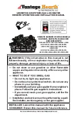
Page 1: ...diatelycallyourgassupplierfromaneighbor s phone Follow the gas supplier s instructions If you cannot reach your gas supplier call the fire department Installation and service must be performed by a qu...

Page 2: ...id fuel burning masonry or UL127 factory built fireplace or in a listed ventless firebox enclo sure It is design certified for these installations in accordance with ANSI Z21 11 2 Exception Do not ins...

Page 3: ...de Gas may be present even though no odor exists Make certain you read and understand all warnings Keep this manual for reference It is your guide to safe and proper operation of this fireplace WARNIN...

Page 4: ...w the instructions in Cleaning and Maintenance page 34 9 Before using furniture polish wax carpet cleaner or similar products turn heater off If heated thevaporsfromtheseproductsmay create a white pow...

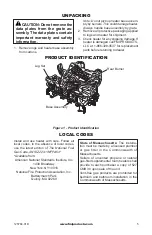
Page 5: ...sembly The data plates contain important warranty and safety information 1 Remove logs and heater base assembly from cartons Note Do not pick up heater base assem bly by burners This could damage hea...

Page 6: ...home owners want their homes as airtight as possible While it is good to make your home energy efficient your home needs to breathe Fresh air must enter your home All fuel burning ap pliances need fr...

Page 7: ...enings add the volume of these rooms to the total volume of the space 2 Multiply the space volume by 20 to determine the maximum Btu Hr the space can support _________ volume of space x 20 Maxi mum Bt...

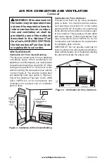
Page 8: ...ure 2 You can also remove door into adjoining room see option 3 Figure 2 Follow the National Fuel Gas Code ANSI Z223 1 NFPA 54 Air for Combustion and Ventilation for required size of ventilation grill...

Page 9: ...s IMPORTANT Vent free heaters add moisture to the air Although this is beneficial installing heater in rooms without enough ventilation air may cause mildew to form from too much moisture See Air for...

Page 10: ...16 from Side Wall Example Carefully follow these instructions This will ensure safe installation into a masonry UL127 listed manufactured fireplace or listed vent free firebox Minimum Clearances For...

Page 11: ...rances Figure 6 Minimum Mantel Clearances Without Using Hood Minimum Noncombustible Material Minimum Noncombustible Material Height Distances to Underside of Mantel Top of Fireplace Opening Underside...

Page 12: ...Hood GA6050 or GA6053 Top of Fireplace Opening Underside of Mantel Shelf Mantel Shelf INSTALLING HEATER BASE ASSEMBLY WARNING You must secure this heater to fireplace floor If not heater will move wh...

Page 13: ...GAS SUPPLY WARNING This appliance requires a 1 2 NPT National Pipe Thread inlet connection to the pressure regulator WARNING A qualified ser vicepersonmustconnectheater to gas supply Follow all local...

Page 14: ...d matter is not likely to freeze A sediment trap traps moisture and contami nants This keeps them from going into heater controls If sediment trap is not installed or is installed wrong heater may not...

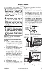
Page 15: ...in gas valve located on or near gas meter for natural gas or using compressed air 4 Check all joints of gas supply piping sys tem Apply noncorrosive leak detection fluid to all joints Bubbles forming...

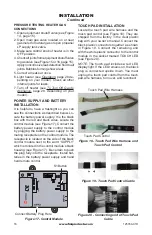
Page 16: ...ule by plugging the battery power supply to the mating receptacle on the control module The receptacle is located on the side of the black control module next to the word SUPPLY which is molded in the...

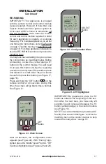
Page 17: ...button see Figure 17 page 16 Press and hold the Off button on the remote control for 40 seconds During this time the screen will go blank this is normal See Figure 21 After 40 seconds the configurati...

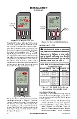
Page 18: ...s If you see signal bars then the remote control has paired properly Go to the next step Press the Back button once to return the highlighted selection to Pairing Press the Middle button and release T...

Page 19: ...ht Log Front Left Log Figure 30 Installing Log Sets Middle Right Log Middle Left Log Bottom Log Pin on Front Left Log 5 Place middle right log over front right and bottom logs as shown in Figure 30 Be...

Page 20: ...lling Log Set Base Assembly Ramp Log Figure 34 Installing Log Set Ramp Log Metal Tab 2 The log must sit flat on the black sheet metal and behind the left metal tab as shown in Figure 34 3 Place front...

Page 21: ...011 1 Top Right Log 015 004 010 1 Small Top Right Log 006 006 006 1 L B G 1 8 R M L B G 2 4 R M L B G 3 0 R M Front Right Log Top Right Log FIBER LOG MODELS LBG 18 24 30 CM Note Your appliance may var...

Page 22: ...gure 40 The two recessed areas fit behind the two grate prongs 4 Position front right log against right side of grate prongs see Figure 41 The two recessed areas fit behind the two grate prongs 5 Plac...

Page 23: ...op log to set in INSTALLATION Continued Figure 44 Installing Middle Log Middle Log Ramp Log Figure 46 Installing Ember Logs Left Ember Log Right Ember Log 7 Place the middle log onto the ramp log as s...

Page 24: ...ack side of this log needs to rest against the front of the base assembly Make sure the flame from the ember pan does not touch the ember bed log CONCRETE LOG MODELS LBG 18 24 30 BM Note Your applianc...

Page 25: ...t log as shown in Figure 52 7 The right middle log has a groove on the bottom to sit on the chassis and has to sit on the tab on the back of the right front The right middle log should have a recess a...

Page 26: ...ft 2 in the center and 3 on the right These numbers are embossed on the back of each piece for identification purposes Please note that BGE18 burner systems do not include ember chunks 11 Rest the mid...

Page 27: ...Platinum Bright Ember placement Add embers to front flat burner Gently remove embers from bag Separate pieces of ember material and place on surface of flat burner just behind horizontal ports as sho...

Page 28: ...oking up to gas supply If so you may have to restart the unit several of times to allow the air to bleed from the system TO TURN OFF GAS TO APPLIANCE 1 Press OFF bottom button on the remote control 2...

Page 29: ...e instructions given by the user desired status and the current situation of the device actual status It also helps us select our choices see Figure 63 A Day of the week B Time C Signal Strength D Sel...

Page 30: ...page 29 Note that a safety temperature can be set in the configuration menu This specifies the maximum the maximum permitted room temperature This temperature can never be set higher than 40 C 104 F...

Page 31: ...s the configuration menu appears see Figure 68 Figure 67 OFF Button Figure 68 Programming Figure 70 Changing No to Yes Figure 69 Highlighting No OPERATION Continued Press the arrow button until Progra...

Page 32: ...mode Night Temp The night temperature is set as desired temperature and the appliance will heat until this temperature is reached Comfort Temp The comfort temperature is set as the desired temperature...

Page 33: ...ME LEVEL 1 To increase the flame level press the up button A beep and a flash of the LED indicate that the system has accepted the order and the flame will increase instantly see Figure 74 2 To decrea...

Page 34: ...mocouple Figure 77 Incorrect Pilot Flame Pattern Your pilot may vary from pilots shown Thermocouple Pilot Burner FRONT BURNER FLAME PATTERN The front burner has a blue flame and should not have any ye...

Page 35: ...f so turn off heater and let cool Remove blockage blocked burner flame holes will create soot Figure 81 Pilot Inlet Air Hole Your pilot may vary from pilot shown Pilot Air Inlet Hole Pilot Assembly Fi...

Page 36: ...21 000 30 000 Btu Hr Type Gas Natural Ignition Electronic Manifold Pressure 4 5 W C Inlet Gas Pressure in of water Max 10 5 W C Min 5 W C BGE2436PE Rating Variable 30 000 39 000 Btu Hr Type Gas Propan...

Page 37: ...system will not function under 3 8 volts and bat teries should be replaced if the voltage is under 4 0 volts 2 Plug power supply box to module see page 16 3 Plug touch pad in module see page 16 figur...

Page 38: ...y any metal or tubing Keep ignitor cable dry 9 Replace wire harness including ignitor cable 10 Replace ods pilot assembly 11 Replace ods pilot assembly 12 Replace control module 13 Ground cable from c...

Page 39: ...ld be hand tight plus 1 4 to 1 2 turn You should not be able to loosen the thermocouple at the control valve with your hand Check the thermocouple terminal connection at the control module If it is lo...

Page 40: ...t in touch pad wiring BUT TON ERROR is shown in remote display 1 Batteries are weak LOW BAT TERY is shown in remote display 1 Fully open equipment shutoff valve 2 Check batteries and replace if needed...

Page 41: ...temperature setting in the remote has shut the burner system off 1 More than one burner system is present and operating on the same frequency 1 Replace control module 1 Follow Re Pairing instructions...

Page 42: ...n burner see Cleaning and Maintenance page 34 or replace burner orifice 2 Replace damaged burner 3 Replace gas regulator 1 Checkburner s fordirtanddebris If found cleanburner s seeCleaning and Mainten...

Page 43: ...d 1 Gas leak See Warning state ment at top of page 2 Control valve or gas control defec tive 1 Foreign matter between control valve and burner 2 Gas leak See Warning state ment at top of page 1 Option...

Page 44: ...cal 1 101137 02 Hardware Kit 1 GA6060 Lava Rock 1 125557 01 Left Ember Chunk 1 1 125557 02 Middle Ember Chunk 2 1 125557 03 Right Ember Chunk 3 1 125070 01 Platinum Embers 1 125071 01 Rockwool Embers...

Page 45: ...ot 1 18 125780 01 Pilot Electric NG 1 125780 02 Pilot Electric LP 1 19 112713 01SA Bracket Pilot 1 112713 02RV Bracket Pilot 1 112713 04 Bracket Pilot 1 20 125489 01 Shield Air 18 BGE 1 125489 02 Shie...

Page 46: ...og 1 3 121699 02 125683 01 125683 01 Middle Right Log 1 4 121699 03 121699 09 121699 15 Middle Left Log 1 5 121699 01 121699 13 121699 13 Bottom Log Remote 1 6 121699 06 121699 12 121699 18 Rear Log 1...

Page 47: ...699 21 Front Right Log 1 6 121699 22 Back Log 1 7 121699 23 Left Small Front Log 1 8 121699 24 Right Small Front Log 1 9 121699 25 Left Control Cover Log 1 10 121699 26 Right Control Cover Log 1 1 2 3...

Page 48: ...55 10 Middle Right Log 1 4 125055 16 125055 05 125055 11 Middle Left Log 1 5 125056 01 125056 02 125056 02 Ramp Log 1 6 125055 14 125055 03 125055 09 Rear Log 1 7 125055 06 125055 06 125055 06 Top Log...

Page 49: ...06 125829 04 Log Rear Right Top 1 7 125827 07 125828 07 125828 07 Log Middle 1 8 125827 08 125828 08 125828 08 Log Top Left 1 9 125827 09 125828 09 125828 09 Log Top Right 1 10 125827 10 125827 10 12...

Page 50: ...og Left Middle 1 7 125851 07 125852 07 125852 07 Log Right Middle 1 8 125851 08 125852 08 125852 08 Log Rear Middle 1 9 125851 09 125852 09 125852 09 Log Rear 1 10 125851 10 125851 10 125851 10 Log Le...

Page 51: ...ntact authorized dealers of this product If they can t supply original replacement part s call FMI PRODUCTS LLC s Technical Ser vice Department at 1 866 328 4537 When calling have ready your name your...

Page 52: ...product and or FMI PRODUCTS LLC who will provide original factory replacement parts Failure to use original factory replacement parts voids this warranty Travel handling transportation diagnostic mat...

Reviews: