I N S T A L L A T I O N
©Vantage, 8/15/2016 / IS-0536-B
InFusion Power Enclosure — MODEL: IMPE-4(2)-IC36(24) & ISPE-4(2)-IC
page 3 of 6
TLM-KIT
T8LRM-KIT
NOTE:
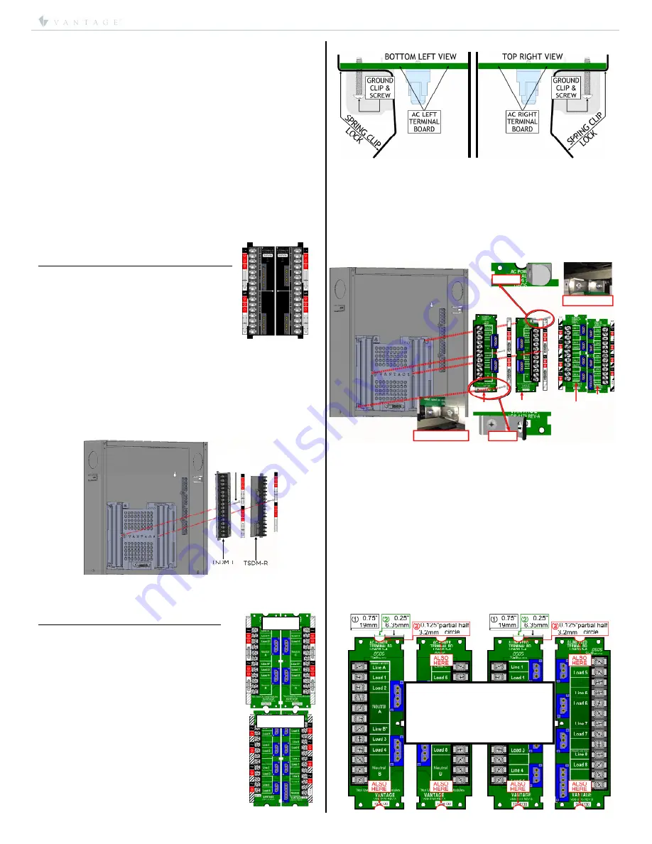
Top Right Clip
Top Right Screw
VSUB172
CLOSE UP
Top Right Clip
CLOSE UP
VSUB173
VSUB160
VSUB161
Bottom Left Clip
NOTE:
Bottom Left Clip
Bottom Left Screw
CAUTION:
In step #3, do not
cut the depth of the notches
more than 0.125” / 3.2mm
deep. The AC Boards should
fit tight from top to bottom.
connect more than one auxiliary device at a time to this power
source. If additional powered devices are needed they must be
separately powered with an external, isolated type (usually no
ground prong), power transformer.
Manual Override
In the unlikely event of a Main Controller failure, the
Manual
Override
can be used to turn selected loads ON. If the system
is in override, individual loads can be controlled by dip-
switches located on each module in the enclosure.
Manual
Override
control can be extended to other enclosures. It is
common to extend
Manual Override
between a Main enclosure
and its Secondary enclosures. It is not recommended to extend
Manual Override
between Main enclosures.
Enclosure AC Terminal Board Types
AC Terminal boards are sold and installed separately. This
allows the installer to use different module models inside the
enclosure. Below are the different types of AC terminal boards
that may be installed in this enclosure.
Terminal Boards For SDM12 Series Modules:
Order kit part #TSDM-KIT
12 Load AC Boards TSDM-L (left) and TSDM-R
(right). Be sure to install the LEFT board’s
center screw for this module’s ground
connection.
Installing SDM12 Module Load Boards – left and TSDM-R right:
1.
Insert AC terminal boards–
TSDM-L left
and
TSDM-R right
to panel board and secure using 1, VHD-0082, #6-32 X
7/8" PHILLIPS PAN HEAD THREAD FORMING screws
(TYPE-F) on each board.
a.
Left board is also the ground connection for the
SDM12-EM module – it must connect to the
enclosure – be careful not to strip self-tapping
threads or damage AC terminal board.
2.
Place module load labels on left and right sides of the AC
panel board using care to align with screw terminals.
3.
Enclosure section is now ready for wiring.
AC Terminal Boards For Legacy Modules
:
Order Kit part #TLM-KIT
MDS8RW101/102 Dim
MDR8RW101/102 Relay
EDIMMOD Electronic Dim
FANMOD Ceiling Fan
SD4008A-120 Dim
SD9008A-277 Dim
AR8008-120 Relay
Order Kit part #T8LRM-KIT
MDR8CW301 Commercial 8-Linefeed, Relay
Be sure to use top left and bottom right
outside screws with all Legacy sets to
accommodate the top and bottom steel-spring
module clips.
Installing Legacy Module Load Board Clips:
Insert AC terminal boards to panel board and secure using
2, VHD-0082, #6-32 X 7/8" PHILLIPS PAN HEAD THREAD
FORMING screws (TYPE-F) on each board. The
bottom left
and
top right
screws should also include the module
spring-clip to lock the module in and provide the module’s
ground source.
NOTE: IMPORTANT,
The
bottom left
and
top right
spring-clips and screws are ground connections for the
module. Note the orientation of the clip locks!
Enclosure section is now ready for wiring.
*NOTE: If using a slightly older version of the
VSUB172
(left)
and
VSUB173
(right) or the VSUB160 (left) and VSUB161 (right)
AC Boards, it will be necessary to cut a slight notch out at the
top and bottom of the board as illustrated below. This will
allow the AC terminal boards to fit into the new
Terminal
Board Module Platform
, part number
103160
.
How To Notch Old Terminal Boards For Use In New Enclosures
STEPS:
1. From the AC Board’s (blue) connectors side measure in
0.75” / 19mm and mark;
2.
From that mark measure another 0.25” / 6.35mm and mark;
3.
Cut a 0.25” / 6.35mm X 0.125” / 3.2mm partial half-circle
notch out of the board on the top and bottom of both the
left and right hand AC boards as illustrated on next page.
Notching Old AC Terminal Boards
Ground
Screw!


