I N S T A L L A T I O N
V A N T A G E C O N T R O L S . C O M
1061 South 800 East • Orem, Utah 84097 • Telephone 801 229 2800 • Fax 801 224 0355
Vantage Thermostat Communication Station— MODEL: Q-ETS3 & STHERR101
Overview
The Q-ETS3, WireLink™ and the STHERR101, RadioLink®
thermostat interface stations provide bi-directional
communication between a Vantage control system and the
HVAC system. Any button or time control using
InFusion
Design Center
or
QLink
software can be programmed to
change Setpoints, Operational Mode, Fan mode and
Occupied/Unoccupied settings on a Vantage thermostat.
Current set points, Indoor/Outdoor temperatures, Operational
Mode, Fan mode and Occupied/Unoccupied (status) may be
displayed on Vantage LCD TouchScreens. A Vantage Q-ETS3
or STHERR101 station and a Vantage thermostat are used
together, in a one-to-one ratio, to control HVAC systems.
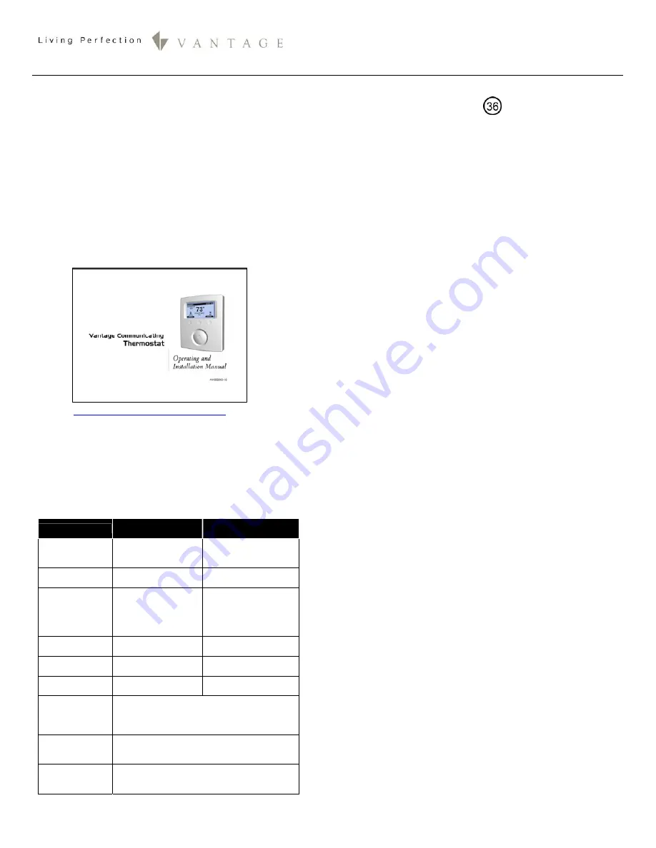
Please completely read, the
Vantage Communicating
Thermostat |Operating and Installation Manual
in conjunction
with this instruction sheet. Click on the manual below:
Or visit:
http://dealer.vantagecontrols.com/
Note: Vantage Controls’ Thermostat is warranted for one year.
This is in contrast with the 5 year warranty carried on most
Vantage products.
System Requirements
Each Vantage thermostat requires one Q-ETS3 or STHERR101
to interface with the Vantage Communicating Thermostat
Part #
STAT
.
Specifications
Q-ETS3
WireLink
STHERR101
RadioLink
Dimensions HWD
3” x 1” x 0.375”
76mm x 25mm x
10mm
4.5” x 1.5” x 0.75”
114mm x 38mm x 19mm
Weight
0.8oz
23g
1.4oz
40g
Station Power
connections*
24V / 36V Station
Bus
and
24Vac from
thermostat base
24Vac from thermostat
base
Station Count
Design Center
0.36W on IC-24
0.54W on IC-36
1 RadioLink Station
Station Count
QLink
1 WireLink Station
1 RadioLink Station
Status LED
Indicator
Yes Yes
Station Bus
Wiring
2C 16AWG, non-shield, <30pF per foot
Station Bus should be separated a minimum
of 18" from other parallel communication
and/or high voltage runs.
Ambient
Operating
Temperature
32-95°F -or- 0-35°C
Ambient
Operating
Humidity
5-95% non-condensing
*CAUTION:
36V stations have a
symbol on the Serial
Number sticker. Any Q-ETS3, not displaying this symbol,
should not be connected to a 36Volt Station Bus.
Software/Firmware
Vantage’s Q-ETS3 & STHERR101thermostat interface stations
are compatible with InFusion Design Center software and
QLink software. NOTE: The
Q-ETS3
requires QLink version 2.50
and Controller firmware version 5.70 or higher. The
STHERR101
requires QLink version 4.0 - build 310 and Controller firmware
version 7.4 or higher. For new projects it is recommended that
firmware and software be kept to the most current release.
Station Connection
Installation of Vantage products should be performed or
supervised by a
Certified Vantage Installer.
The Q-ETS3
connects to the Vantage System Station Bus with the two
black wires labeled Station Bus. The Station Bus wire should
comply with the Vantage Station Bus wiring specification. The
STHERR101 connects to the Vantage System via a RadioLink™
enabled system.
Mounting the Q-ETS3 or STHERR101
The Q-ETS3 or STHERR101 may be mounted behind the
thermostat in a single gang box or may hang through a 1
¾
”
(4.44cm) hole in the wall. The Black wire X1 and Green wire
X2 attach to terminals labeled X1 & X2 of the thermostat sub
base. The Red wire 24V attaches to the R terminal (screw
terminals on right) of the thermostat sub base along with the
24V power source.
The Q ETS3 or STHERR101 do not supply
power to the thermostat.
Please see the
Vantage Communicating Thermostat |Operating
and Installation Manual
for each of the following topics:
•
Configuration, Q-ETS3, WireLink™
•
Configuration, STHERR101, RadioLink®
•
Status LED Diagnostic Information for Q-ETS3 or
STHERR101
•
Thermostat Setup with InFusion
•
Thermostat Setup with QLink
•
External Sensors
•
Temperature Averaging
Globally Display Outdoor Sensor
In
Design Center
, click on
Settings | Project Preferences |
Thermostat
and the Global Sensor drop down list. Select the
thermostat that has the external sensor. In
QLink
Select
Use as
the Globally Displayed External Sensor
from the Thermostat
Station properties window. This will broadcast the value of the
external sensor to all other thermostats connected to the
Vantage System. If
Use as the Globally Displayed External
Sensor
is not checked,
other
thermostats on the system will
not display the outdoor temperature.
Occupied (formerly Auto(Day)) and Unoccuped (formerly
(Night)) Modes
Most Thermostat Functions only work when the thermostat is
in Occupied (formerly Auto(Day)) Mode. If the thermostat is in
Unoccupied (formerly Manual(Night)) mode, the thermostat
automatically changes to Occupied when a command is
received. However, it is possible to end any task with a
command to leave the thermostat in Occupied or Unoccupied
modes as desired.


