background image

○ ○ ○ ○ ○ ○ ○ ○ ○ ○ ○ ○ ○

23

○○○○○○○○○○○○○○○○○○○○○

○○○○○○○○○○○○○○○○○○○○○○○○○○○○○○○○○○○○○○○○○○○○○○○○○○○○○○○○○○○○○○○○

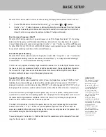
When the SETUP button selects Center and Surround Delay, the Display Panel will read “DELAY” and “ms”.

1.

Use the SPEAKER button to select either the center “

“ or surround “

” speakers.

2.

Use the “+” or “-” buttons to increase or decrease the delay by one millisecond (1ms/step). The delay
should be increased by one millisecond for every foot the center or surround speaker is closer to the
listener than the main speakers. (Sound travels at about 1 foot per millisecond.)

Bass Crossover Frequency Cutoff

When the SETUP button selects Bass Crossover Frequency Cutoff, the Display Panel reads “Fc”. This setting
determines the frequency cutoff for redirection of the bass information to the subwoofer or other speaker
channels (depending on the speaker configuaration). Use the “+” and “-” buttons to set the cutoff frequency
for either MAX (120 Hz), STD (100 Hz) or MIN (80 Hz). For best sound reproduction, your five speakers should
be capable of producing sound down to the selected frequency.

Karaoke Playback Decoding

When the SETUP button selects Karaoke, the Display Panel reads “KAR”. Using the “+” and “-” buttons this
Karaoke playback decoding mode can be enabled or disabled. When “y” is displayed Karaoke decoding is
enabled. When “ n “ is displayed Karaoke decoding is disabled.

This feature is only applicable for Dolby Digital encoded Karaoke sources. On Dolby Digital Karaoke sources
the two voice tracks are encoded on the left and right surround channels. To properly playback these disks
the surround left & right channels  should be down-mixed into the main left and right channels. When
Karaoke is enabled, Karaoke sources will be properly down-mixed.

Speaker Trim with Test Tones

When the SETUP button selects Speaker Trim with Test Tones, the Display Panel will read “TRIM” and “dB”.
Additionally, a test tone will be generated into all the enabled speakers for two seconds. “VOL SYNC” is
displayed to indicate successful volume tracking. VTRACK™ will not be engaged and “VOL SYNC” will not
be displayed if manual volume mode is selected (see the section titled Front Panel Controls - Volume Sync).

The test tone will then cycle through the entire speaker array in a circular pattern, sending a tone to each
speaker for two seconds. The corresponding speaker icon is displayed. This test tone pattern continues until
the speaker balancing procedure is completed. Listen to the tone as it cycles through a couple times to
determine which speaker(s) needs to be trimmed up or down.

The object of this procedure is to adjust the speaker levels so they are all reproducing the same relative
volume level. Use the “+” and “-” buttons to trim the speaker output level. The adjustment levels are
measured in decibels (dB) and shown on the display. The test tone can only be heard on the speakers that
were enabled during the Speaker Configuration procedure.

The control range for the trim level is -10dB to 10dB for all the speakers except the subwoofer. The control
range for the subwoofer is -20dB to 0dB.

BASIC SETUP

QUICK FACTS

The Speaker Trim with
Test Tones should be
performed at least
once to allow the unit
to automatically learn
certain parameters
of your stereo amp.
It calculates the phase
and delay of the stereo
amp so that the
DPA-S50’s three
amplifiers are perfectly
matched to the existing
stereo amp. This will also
assure accurate
VTRACK™ operation.
For more accurate
measurements,set the
master volume to a
moderate to loud
listening level.

Summary of Contents for DPA-S50

Page 1: ...1 Digital Surround Processor Amplifier OWNER S MANUAL DPA S50...

Page 2: ...et appareil num rique de la classe B respecte toutes les exigences du R glement sur le mat riel brouilleur du Canada The lighting flash with arrowhead within the equilateral triangle is intended to al...

Page 3: ...at the unit is faulty 1 Read Owner s Manual To assure the finest performance please read this manual carefully All the safety and operating instructions should be read before the product is operated 2...

Page 4: ...tem Configuration Thermally Protected Power Amplifier 20 bit Digital to Analog D A Converters on all 6 Channels Dual Transformer Design Dedicated Toroid for the Amplifier Test Tone Generator for Accur...

Page 5: ...Panel Connections System Connections Front Panel Controls Speaker Placement Surround Modes Operating Your Stereo System with the DPA S50 Basic Setup Advanced Setup Troubleshooting Servicing Specifica...

Page 6: ...the DPA S50 to external amplifiers When used with a 5 1 Ready receiver integrated amp or external amplifiers the DPA S50 s internal amplifiers can be disabled converting the DPA S50 into a stand alone...

Page 7: ...p are used to hook up the DPA S50 s MAIN AUDIO LINE OUT a duplicate set of TAPE PLAY IN jacks are provided for reconnecting a cassette deck Connect the tape play out jacks of the cassette deck to the...

Page 8: ...to your stereo amp s left and right speaker terminals The MAIN SPEAKER IN signal is always passed through to the MAIN SPEAKER OUT and your stereo amp is always driving the main speakers 8 SPEAKER OUT...

Page 9: ...he system connection process Just be aware that the DPA S50 doesn t have separate left and right jacks for the center sub and digital inputs and you can use any color plug Make sure all interconnect c...

Page 10: ...R L R L R L R L R LD TV DIGITAL IN LD TV DVD CD DVD CD SURROUND RT LT CENTER AUDIO INPUT VCR TAPE OUT TAPE REC TAPE PLAY IN CENTER SUB MAIN SURROUND AUDIO LINE OUT MAIN RT MAIN LT MAIN RT MAIN LT DPA...

Page 11: ...onnect the DPA S50 s CENTER SPEAKER OUT terminals to the center loudspeaker If you use a powered center speaker connect the DPA S50 s CENTER AUDIO LINE OUT to the center loudspeaker s amplifier 5 Conn...

Page 12: ...nstructions and follow this diagram and instruction for the hook up of the center channel speaker Connect the DPA S50 s CENTER AUDIO LINE OUT to the powered speaker s line input jack SYSTEM CONNECTION...

Page 13: ...ing device s tape play out is being monitored If the source being recorded is connected to the DPA S50 the source not the recording device is monitored QUICK FACTS When a digital source is selected th...

Page 14: ...re explained in the Advanced Setup section Disable Amplifiers Connecting the DPA S50 to a 5 1 Ready A V Receiver Integrated Amp It is possible to integrate the DPA S50 into a system that already has a...

Page 15: ...lso be connected to the DPA S50 s AUDIO INPUT jacks as shown in the following diagram L L R L R L R LD TV DIGITAL IN LD TV DVD CD DVD CD AUDIO INPUT VCR TAPE DPA S50 REAR ANALOG AUDIO SOURCE 1 ANALOG...

Page 16: ...of front panel will control the volume on all six channels The volume setting measured in decibels dB appears in the Display Panel When you press and hold this button down for a few seconds a test ton...

Page 17: ...ack may not be heard clearly By compressing the data the original soundtrack s overall dynamic range is reduced without affecting the dialog level The MIN setting provides the greatest compression pos...

Page 18: ...ection titled Basic Setup 9 BUTTONS During manual volume mode see VOLUME SYNC on page 16 the and buttons increase or decrease the master volume in all six channels These buttons also make adjustments...

Page 19: ...urround Speakers Place the left and right surround speakers off to the side or slightly behind the main listening position They should be approximately two to three feet above the ear level of a seate...

Page 20: ...discs videotapes many TV Cable broadcasts etc When a 2 ch source analog PCM MPEG or 2 ch Dolby Digital is played on the DPA S50 the Pro Logic processor decodes the signal and properly distributes the...

Page 21: ...which should have been properly connected to the DPA S50 If this connection has not been made yet refer to section SYSTEM CONNECTIONS Your stereo amp now powers the main channels that are decoded by...

Page 22: ...use the or buttons when the is blinking Configure a speaker wide only if it can reproduce deep base down to 20 to 35 Hz 3 If you want to disable a speaker altogether press the button when that speake...

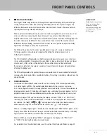
Page 23: ...operly down mixed Speaker Trim with Test Tones When the SETUP button selects Speaker Trim with Test Tones the Display Panel will read TRIM and dB Additionally a test tone will be generated into all th...

Page 24: ...d portion of the center image into the main channels is tracked by VTRACK Maximum Manual Volume Setting When the DPA S50 is in the manual volume mode see the section titled Front Panel Controls Volume...

Page 25: ...a stand alone decoder when used with a 5 1 Ready receiver integrated amp or external power amplifiers If you wish to operate the DPA S50 in this configuration we recommend disabling the DPA S50 s int...

Page 26: ...the speaker configuration see Basic Setup Hum from Speakers Improper cable connections or need Check that all interconnect cables are firmly in low frequency isolation place Disconnect any connection...

Page 27: ...ial along with a written explanation of the problem Be sure to clearly mark the outside of the carton with the Return Authorization Number given to you If the problem is covered by the warranty you mu...

Page 28: ...kHz D A converters 20 bits 96kHz Sampling frequencies 48kHz 44 1kHz 32kHz Bass crossover Frequencies 80Hz 100Hz 120Hz Filter response 12dB oct Center channel delay 0 5ms in 1ms step Surround channel d...

Page 29: ...29 1999 by VANTAS...

Page 30: ...31 3715 Doolittle Drive Redondo Beach CA 90278 Phone 310 297 5700 Fax 310 297 5757 www vantas com...

Reviews: