This warranty does not cover cosmetic damage or damage due to acts of God, accident, misuse,
abuse, negligence, commercial use, or modification of or to any part of the Product. This warranty
does not cover damage due to improper installation, operation, or maintenance. This warranty is
limited to the original purchaser and is not transferable. In no case shall our company’s liability
exceed the original cost of the purchased product and will not cover consequential, incidental or
collateral damage. Our company reserves the right to inspect any and all equipment involved in a
warranty claim. Repair or replacement decisions are at the sole discretion of our company. Further,
our company reserves the right to change or modify this warranty without notice.
REPAIR OR REPLACEMENT AS PROVIDED UNDER THIS WARRANTY IS THE EXCLUSIVE
REMEDY OF THE CONSUMER.
As our company has no control over use, setup, final assembly, modification or misuse, no liability
shall be assumed nor accepted for any resulting damage or injury. By the act of use, setup or
assembly, the user accepts all resulting liability.
If you as the purchaser or user are not prepared to accept the liability associated with the use
of this product, you are advised to return this product immediately in new and unused
condition to the place of purchase.
AM50401 Fuselage for 30cc Edge 540
AM50402 Fiberglass Painted Cowling for 30cc Edge 540
AM50403 Canopy for 30cc Edge 540
AM50404 Rudder for 30cc Edge 540
AM50405 Left Wing Panel w/ Aileron for 30cc Edge 540
AM50406 Right Wing Panel w/ Aileron for 30cc Edge 540
AM50412 Left Stabilizer w/ Elevator for 30cc Edge 540
AM50413 Right Stabilizer w/ Elevator for 30cc Edge 540
AM50416 Landing Gear for 30cc Edge 540
AM50417 Wheel Pants for 30cc Edge 540
AM50420 Wing Tube for 30cc Edge 540
AM50421 Stabilizer Tube for 30cc Edge 540
AM50422 Decal Set for 30cc Edge 540
Contents of Kit
A 7-channel or greater computer radio is highly recommended. This allows the following features:
• Mixing the right aileron to the left aileron (flaperon mix)
• Electronically adjustable aileron differential
• Mixing the right elevator to the left elevator (dual elevator mixing)
• Independent travel and trim adjustments of each elevator half
When you use a 7-channel or greater computer radio, each servo is plugged into its own separate
channel. Consult your radio manual for specific details on hookup and programming.
Control Throws
Correctly balancing an aerobatic model is critical
to its performance and flight characteristics.
Checking the balance on this model is best done
with two people.
Step 1
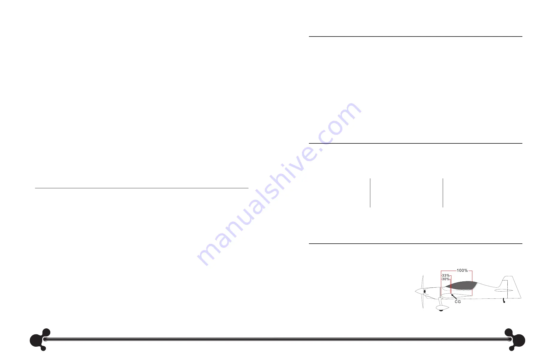
Measure back 30%-33% of the whole wing root’s
length from the leading edge and mark the CG
range with a felt-tipped pen at the wing tip. This is
the recommended center of gravity (CG) range.
Recommended Center of
Gravity (CG)
The following is our recommended control throws for your reference.
2
19
20
°
up
20
°
down
40
°
up
40
°
down
15
°
up
15
°
down
26
°
left
26
°
right
40
°
up
40
°
down
43
°
left
43
°
right
Standard
3D
Standard
3D
3D
Standard
Elevator
Rudder
Aileron
Radio Setup


