The servos used for the control surfaces of this model must have a minimum of 6kg-cm (85 oz-in)
of servo torque. The servos with metal gear are strongly recommended.
Before beginning the assembly of the model, remove each part from its bag for inspection. Closely
inspect the fuselage, wing panels, rudder, and stabilizer for damage. If you find any damaged or
missing parts, contact the place of purchase.
If you find any wrinkles in the covering, use a heat gun or covering iron to remove them. Use caution
while working around areas where the colors overlap to prevent separating the colors.
Radio Equipment
• 4-channel radio system (minimum)
• 1 standard servo for throttle
• 5 hi-torque servos
Recommended Engines
• D-30, R-26, Q-26
• Propeller (consult engine instructions)
• Servo Extensions
• Y-Harness
Adhesives
• 6-minute epoxy
• 30-minute epoxy
• Thick CA glue
• Threadlock
Additional Required Items
Tools
• Adjustable wrench (small)
• Drill (drill press preferred)
• Hook and loop straps
• Foam
• Hex wrench
• Hobby knife
• Phillips screwdriver (small)
• Pliers
• Scissors
• Square
• Measuring device (e.g. ruler, tape measure)
Servo Selection
Before Starting Assembly
18
3
Step 9
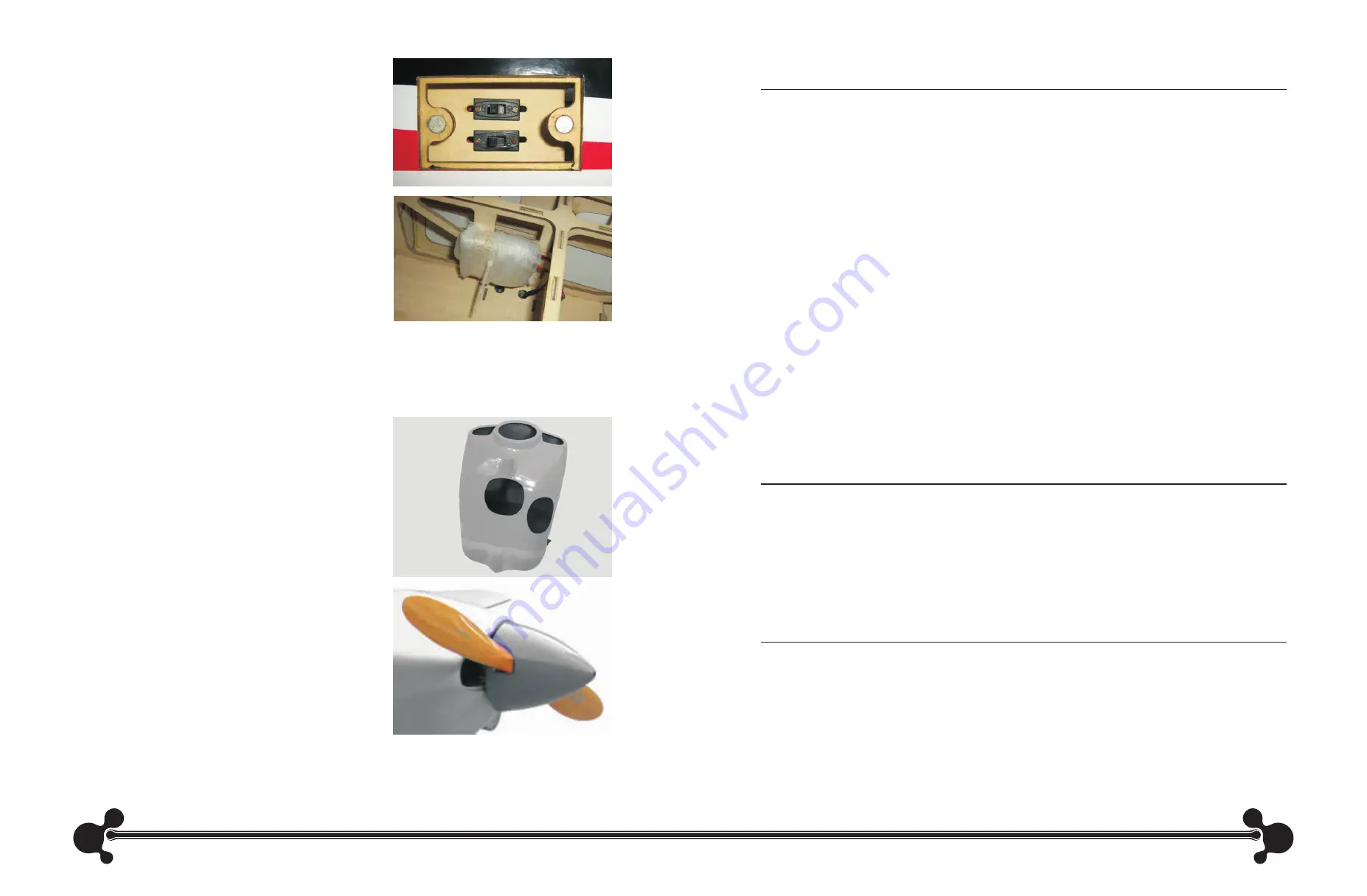
Install the switch for the ignition in the switch hatch on the
side of the fuselage as shown.
Note: As the cowling mounting screw is inside the fuselage under the hatch, you need to open
the hatch before accessing the screw. To open the hatch, just remove the screws holding it on
both sides of the fuselage and lift the hatch from the fuselage.
Step 10
Secure the battery for the ignition inside the fuselage
using a hook and loop strap. Make sure to add a few
pieces of foam between the fuselage and battery to
prevent damage to the battery caused by vibration.
Connect the battery to the ignition switch.
Step 12
Route the vent line from the fuel tank out of the bottom of the cowling.
Step 11
Attach the fuel line from the fuel tank to the carburetor. Make sure the line is from the clunk and not
the vent line.
Step 13
Make any necessary cutouts to clear the engine
components in the cowling. Remove a section
from the bottom of the cowling near the exhaust
pipe for cooling outlet as shown. This opening is
necessary to allow cooling air to pass through
the cowling to prevent overheating of your engine.
Step 14
Slide and lock the cowling to the fuselage and
then secure the cowling with a screw. Mount the
propeller and spinner to complete the procedure.


