background image

FPA-C34, FPA-W34   


15

17


This


device


complies


with


FCC


class


B


Rules.


Operation


is


subject


to


the


Following


conditions.


This


device


may


not


cause


harmful


interference.


This


device


must


accept


any


interference


received,


including


interference


that


may


cause


undesired


operation.


Note:


This


equipment


has


been


tested


and


found


to


comply


with


the


limits


for


a


Class


B


digital


device,


pursuant


to


part


15


of


the


FCC


Rules.


These


limits


are


designed


to


provide


reasonable


protection


against


harmful


interference


in


a


residential


installation.


This


equipment


generates,


uses


and


can


radiate


radio


frequency


energy


and,


if


not


installed


and


used


in


accordance


with


the


instructions,


may


cause


harmful


interference


to


radio


communications.


However,


there


is


no


guarantee


that


interference


will


not


occur


in


a


particular


installation.


If


this


equipment


does


cause


harmful


interference


to


radio


or


television


reception,


which


can


be


determined


by


turning


the


equipment


off


and


on,


the


user


is


encouraged


to


try


to


correct


the


interference


by


one


or


more


of


the


following


measures:


—Reorient


or


relocate


the


receiving


antenna.


—Connect


the


equipment


into


an


outlet


on


a


circuit


different


from


that


to


which


the


receiver


is


connected.


—Consult


the


dealer


or


an


experienced


radio/TV


technician


for


help.


Any


modification


to


the


product


is


not


permitted


unless


authorized


by


Vantron.


It’s


not


allowed


to


disassemble


the


product,


it


is


not


allowed


to


replace


the


system


or


change


components


unless


with


permission


and


certification.


Please


contact


the


technical


support


department


of


Vantron


or


local


branches


for


help.


Summary of Contents for FPA-C34

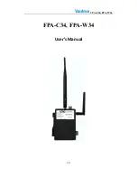
Page 1: ...FPA C34 FPA W34 1 17 FPA C34 FPA W34 User s Manual ...

Page 2: ...17 2 V1 1 Add DIP Switch explain 2015 01 25 3 V1 2 Add some pictures to function 2015 02 01 4 V1 3 Change some pictures to function 2015 02 04 5 V1 4 Statement Vantron is the manufacturer to the device and SMC is the customer of the device 2016 7 19 6 V1 5 Require professionally install antennas and use antennas specified by the manufacturer 2016 8 3 ...

Page 3: ...s for Power Cables and Accessories 5 2 Overview 7 2 1 Introduction 7 3 M2M Gateway FPA C34 FPA W34 Hardware Instructions 9 3 1 Product Appearance 9 3 5 Interface Description 10 3 5 1 Power Interface 10 3 5 2 Ethernet Interface 10 3 5 3 RS232 or RS485 Connector 11 3 5 3 DIP Switch for select 11 3 5 3 DIP Switch for boot 11 3 5 6 LED 12 3 5 7 Micro SIM Card 12 3 5 8 DEBUG 12 3 5 9 Renew button 12 3 ...

Page 4: ...logy Vantron E mail sales vantrontech com The trademarks and registered trademarks in this manual are properties of their respective owners No part of this manual may be copied reproduced translated or sold No changes or other purposes are permitted without the prior written consent of Vantron Vantron reserves the right of all publicly released copies of this manual 1 2 Notes Applicable notes are ...

Page 5: ... attention to the product labels safety instructions printed on silk screens Do not try repairing this product unless declared in this manual Keep away from heat source such as heater heat dissipater or engine casing Do not insert other items into the slot if any of this device Keep the ventilation slot ventilated for cooling System fault may arise if other items are inserted into this device Inst...

Page 6: ...t use spray detergent Clean with a damp cloth Do not try cleaning exposed electronic components unless with a dust collector Support for special fault Power off and contact technical support personnel of Vantron in case of the following faults The device is damaged The temperature is excessively high Fault is still not solved after the operation according to the manual ...

Page 7: ...t stably and assemble its antenna s for WLAN BlueTooth CELL and possible GPS if the device is configured for CELL function maybe you need to activate the SIM card against proper carrier and then please insert correct 12 24V DC cable to the power jack of the device the device will be powered up and the PWR LED lighting indicates the system boots up The device have a standard RJ45 Ethernet port whic...

Page 8: ...FPA C34 FPA W34 8 17 ...

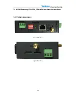
Page 9: ...FPA C34 FPA W34 9 17 3 M2M Gateway FPA C34 FPA W34 Hardware Instructions 3 1 Product Appearance Front Side View Light Side View ...

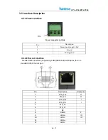
Page 10: ...Power input range 12 24V 2 Ground 3 Shell ground 3 5 2 Ethernet Interface Standard RJ45 interface supporting 10M 100M Full Half Duplex this is a standard RJ45 Ethernet port Pin Description Remarks 1 ETH_TX O 2 ETH_TX O 3 ETH_RX I 4 ETH_RX I 5 ETH_CT 6 ETH_CT 7 NC 8 DGND P 9 LEDG IO 10 LEDG IO 11 LEDG 12 LEDG PIN1 ...

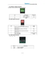
Page 11: ... 5 3 DIP Switch for select Bit Description Single 1 ON have matched resistance of 120 ohm OFF have no Term 2 ON have pull up resister of 510 ohm OFF have no Bias 3 ON have pull down resister of 510 ohm OFF have no Bias 4 ON select RS232 OFF select RS485 Select RS232 or RS485 3 5 3 DIP Switch for boot Note 1 off 0 on Bit 4 1 Description 1111 Boot for SD MMC 1011 Boot for NAND ...

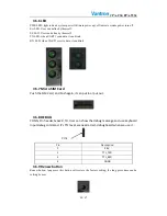
Page 12: ...ceive data it can blink 3 5 7 Micro SIM Card Push the SIM Card and Push again it can put in or put out 3 5 8 DEBUG CONN Pin header 1x4x2 0 TH User can show the debug message and use keyboard input debug command It s TTL level we need a Uart debug board when we use it Pin Description 1 3 3V 2 TTL_TXD 3 TTL_RXD 4 DGND 3 5 9 Renew button Renew button long press this button will restore the factory se...

Page 13: ...FPA C34 FPA W34 13 17 3 5 12 SD MMC socket This is standard SD card socket user can save data on this storage ...

Page 14: ...d to open the enclosure to adjust and replace the structure and components of the device Do not change components unless the power cord is removed In some cases the device may still have residual voltage even if the power cord is removed Therefore it is a must to remove and fully discharge the device before contact so as to avoid injury Unauthorized changes to this product or its components are pr...

Page 15: ...rence to radio communications However there is no guarantee that interference will not occur in a particular installation If this equipment does cause harmful interference to radio or television reception which can be determined by turning the equipment off and on the user is encouraged to try to correct the interference by one or more of the following measures Reorient or relocate the receiving a...

Page 16: ...mpts L exploitation est autorisée aux deux conditions suivantes 1 l appareil ne doit pas produire de brouillage et 2 l utilisateur de l appareil doit accepter tout brouillage radioélectrique subi même si le brouillage est susceptible d en compromettre le fonctionnement RF exposure warning This equipment must be installed and operated in accordance with provide instructions and the antenna used for...

Page 17: ...China Office Chengdu Vantron Technology Ltd Address 6th floor 1st building No 9 3rd WuKe East Street WuHou District Chengdu P R China 610045 Tel 86 28 8512 3930 3931 8515 7572 6320 Email sales vantrontech com cn US Office Sierra Monitor Corporation Address 1991 Tarob Court Milpitas CA 95035 6840 UNITED STATES Tel 1 408 964 4447 Fax 1 408 262 9042 ...

Reviews: