background image

                                                                                VT-


M2M-Ruban 


12

 / 27 


View


for


all


optional


embedded


modules


and


antennas


Summary of Contents for VT-M2M-Ruban

Page 1: ...All Rights Reserved VT M2M Ruban User s Manual Vantron Technology Ltd www vantrontech com ...

Page 2: ...story No Version Description Date 1 V1 0 First release Oct 10 2014 1 V1 1 Update the default DDR memory to 512MB for Moon Island usage Feb 3 2015 2 V1 2 1 Update the order code 2 Add the Ethernet interface describe Feb 04 2015 ...

Page 3: ... for Power Cables and Accessories 7 2 Overview 9 2 1 Introduction 9 2 2 Product Series 10 2 2 1 Product Order Coding Rule 10 2 2 2 Ordering Information 10 3 M2M Ruban Hardware Instructions 11 3 1 Product Appearance 11 3 2 Specifications 13 3 3 Dimension 16 3 4 Interface Description 17 3 4 1 Wide Range Power Interface 17 3 4 2 Ethernet Interface 18 3 4 3 D Sub 9 RS232 Connector 19 3 4 4 D Sub 9 RS2...

Page 4: ...VT M2M Ruban 2 27 3 4 6 USB Host Connector 21 3 5 Operation Notice 22 3 5 1 Change SIM Card 22 3 5 2 Power Supply 22 4 Tips 23 ...

Page 5: ...r the software Please contact our technical department for relevant operation solutions if there is any problem that cannot be solved according to this manual Vantron reserves all rights of this manual including the right to change the content form product features and specifications contained herein at any time without prior notice The latest version of this manual is at www vantrontech com cn Pl...

Page 6: ... 2 Notes Applicable notes are listed in the following table Sign Notice Type Description Notice Important information and regulations Caution Caution for latent damage to system or harm to personnel 1 3 Statement It is recommended to read and comply with this manual before operating VT M2M Ruban which provides important guidance and helps decreasing the danger of injury electric shock fire or any ...

Page 7: ...safety instructions on device label Vantron assumes neither warranty nor legal liability even if the device is still under warranty 1 6 Safety Instructions Keep and comply with all operation instructions warnings and information Pay attention to warnings on this device Read the following precautions so as to decrease the danger of injury electric shock fire or any damage to the device ...

Page 8: ...ater heat dissipater or engine casing Do not insert other items into the slot if any of this device Keep the ventilation slot ventilated for cooling System fault may arise if other items are inserted into this device Installation ensure correct installation according to instructions from the manufacturer with recommended installation tools Ensure ventilation and smoothness according to relevant ve...

Page 9: ... technical support personnel of Vantron for any uncertainty about the requirements of necessary power source Use tested power source This product still contains a button lithium battery as a real time clock after its external power source is removed and therefore should not be short circuited during transportation or placed under high temperature Place cables properly Do not place cables at any pl...

Page 10: ...cloth Do not try cleaning exposed electronic components unless with a dust collector Support for special fault Power off and contact technical support personnel of Vantron in case of the following faults The device is damaged The temperature is excessively high Fault is still not solved after the operation according to the manual ...

Page 11: ...ded devices equipped with the state of the art technology and the best product services Vantron s M2M products are based on the most advanced ARM and Intel Atom processors and have low power consumption and high integration The products are designed for applications of M2M in industrials medicals financial retail vehicle and transportations etc ...

Page 12: ...h GPRS 3G VT M2M Ruban 4 512M 8GF 3GZW Quark Processor 400MHz CPU 512MB DDR3 8G Flash GPRS 3G ZigBee Accessories Install Mechanical tools 1pc Power Adapter with locked connector Optional 1pc Power Terminal 1x3x5 08mm 1pc 3G Antenna Optional 1pc WiFi Antenna Optional 1pc Zigbee Antenna Optional 1pc GPRS Antenna 1pc Order Code VT M2M Ruban 4 256M 8GF 3GZW W Extended Temperature Z Zigbee 3G 3G CPU Sp...

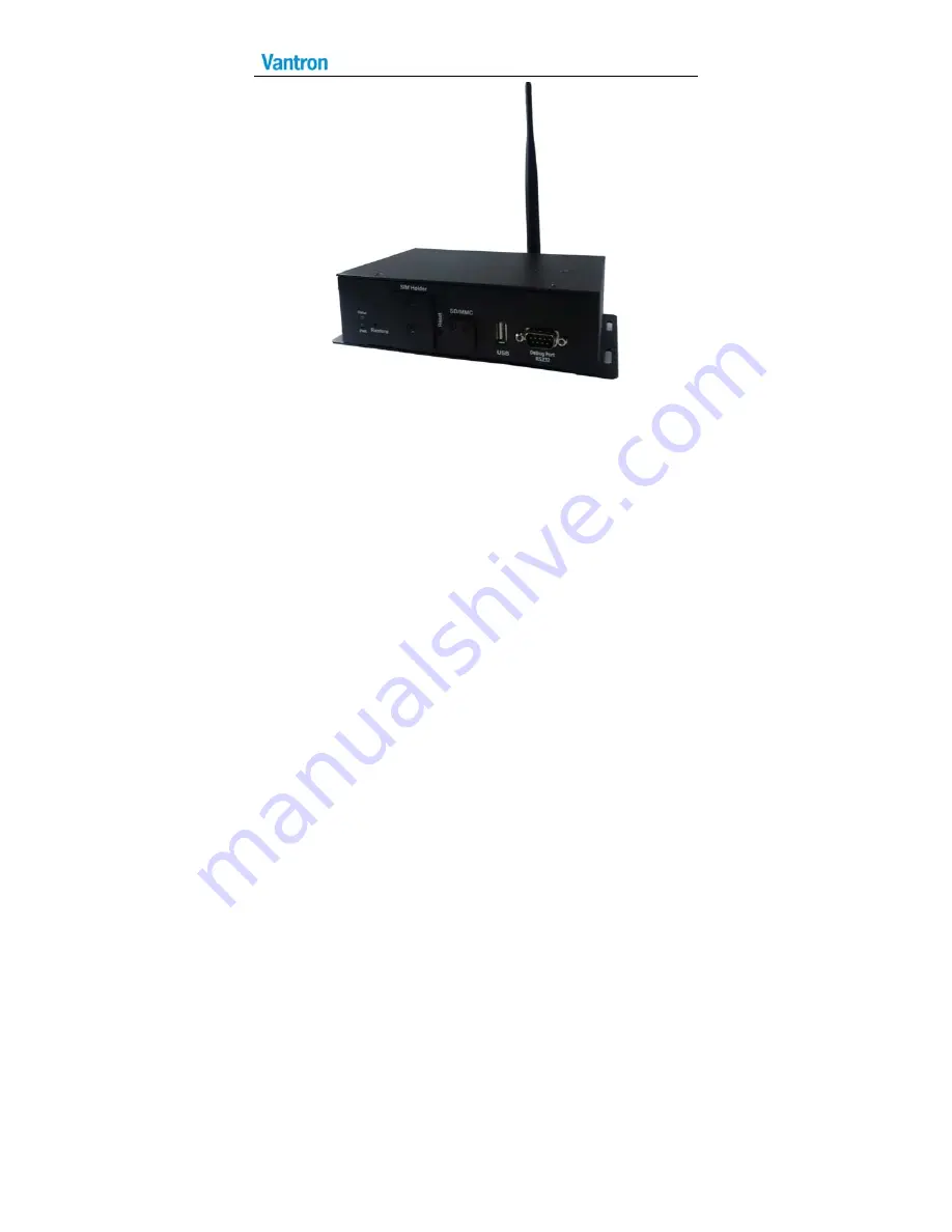
Page 13: ...VT M2M Ruban 11 27 3 M2M Ruban Hardware Instructions 3 1 Product Appearance Front Side View Back Side View ...

Page 14: ...VT M2M Ruban 12 27 View for all optional embedded modules and antennas ...

Page 15: ...Ruban 13 27 Bottom View for optional embedded modules 3 2 Specifications Specifications CPU Processor Intel ATOM Quark SoC A0 X1021 400Mhz Memory On Board RAM DDR3 800MT s 512MB Optional 256MB 1GB Down Memory ...

Page 16: ...external antenna Peripheral Interfaces Ethernet 2x10 100 BaseT RJ45 USB 1xUSB2 0 Host Type A COM Port 2xRS232 or RS485 DB9 Male External SD card 1x Micro SD card Slot RTC Supported Control Reset Button Restore Recovery Button Software OS Linux Applications SDK Available Power Input DC24V 9 36V 1x3x5 08MM Consumption 6W Pulse8W Sleep 1W without 3G GPRS Zigbee WLAN Mechanical Dimensions 138x102x52mm...

Page 17: ...nvironment Condition Temperature Operating 0 C 60 C ETR 40 C 80 C Optional Storage 20 C 70 C ETR 40 C 85 C Optional Humidity 5 95 RH at 25 35 Non Condensation Cooling Mode Fan less Heat Sink Approvals UL FCC Class B and CE ...

Page 18: ...VT M2M Ruban 16 27 3 3 Dimension ...

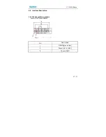
Page 19: ...VT M2M Ruban 17 27 3 4 Interface Description 3 4 1 Wide Range Power Interface Power JACK 1x3x5 08MM Pin Description 1 DGND ground pin 2 Power 6 to 36V 3 Chassis GND No 1 ...

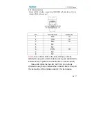
Page 20: ... IO 4 NC 5 NC 6 RDN IO 7 NC 8 NC NOTE Green LED of RJ45 is the LED_LINK pin in Mode 2 Default mode will be ON to indicate Link is good and BLINK to indicate activity is present on either transmit or receive activity Yellow LED of RJ45 is the LED_ACT COL pin In Mode 2 Default mode this pin indicates the Collision status of the port The LED will be ON for Collision and OFF for No Collision ...

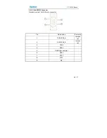
Page 21: ...ban 19 27 3 4 3 D Sub 9 RS232 Connector Standard vertical 2x DB 9 male connector Pin Description Remarks 1 DCD1 485_A Jumper set 2 RXD1 485_B Jumper set 3 TXD1 4 DTR1 5 DGND ground pin 6 DSR1 7 RTS1 8 CTS1 9 NC ...

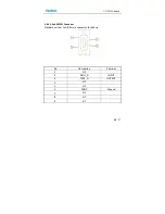
Page 22: ...VT M2M Ruban 20 27 3 4 4 D Sub 9 RS232 Connector Standard vertical 1x DB 9 male connector for debug Pin Description Remarks 1 NC 2 RXD1_D INPUT 3 TXD1_D OUTPUT 4 NC 5 NC 6 DGND Ground 7 NC 8 NC 9 NC ...

Page 23: ...light system power OK main power up off system power turn off Status LED Blink SATA HDD active 3 4 6 USB Host Connector Dual vertical USB A type interface USB2 0 Pin Description A1 USB1_VCC 5VDC A2 USB1_D A3 USB1_D A4 USB1_DGND ground pin ...

Page 24: ... Card Push the small button on the left of SIM Card Holder and install the SIM card to the holder Then push the holder into the Slot 3 5 2 Power Supply Please make sure using adapter in the accessory or the power is not reversed when powered by other adapter ...

Page 25: ...s with the sign of explosive should not be disposed like household waste but delivered to specialized electrical electronic waste recycling disposal center Proper disposal of this sort of waste helps avoiding harm and adverse effect upon surroundings and people s health Please contact local organizations or recycling disposal center for more recycling disposal methods of related products Comply wi...

Page 26: ...re it is a must to remove and fully discharge the device before contact so as to avoid injury Unauthorized changes to this product or its components are prohibited In the aim of avoiding accidents as far as possible it is not allowed to replace the system or change components unless with permission and certification Please contact the technical department of Vantron or local branches for help Pay ...

Page 27: ...erference that may cause undesired operation Note This equipment has been tested and found to comply with the limits for a Class B digital device pursuant to part 15 of the FCC Rules These limits are designed to provide reasonable protection against harmful interference in a residential installation This equipment generates uses and can radiate radio frequency energy and if not installed and used ...

Page 28: ...ng two conditions 1 This device may not cause interference 2 This device must accept any interference including interference that may cause undesired operation of the device RF exposure warning This equipment must be installed and operated in accordance with provide instructions and the antenna used for this transmitter must be installed to provide a separation distance of at least 20 cm from all ...

Page 29: ...07 Sunnyvale CA 94086 Tel 510 304 7666 Email sales vantrontech com China Office Chengdu Vantron Technology Ltd Address 3rd floor 3rd building No 9 3rd WuKe East Street WuHou District Chengdu P R China 610045 Tel 86 28 8512 3930 3931 8515 7572 6320 Email sales vantrontech com cn ...

Reviews: