Vantron
| Embedded in your success, Embedded in your better life
World-leading provider of embedded/IoT products and solutions
VT-SBC-RK3568-NT | User Manual 15
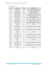
Pinout description:
Pin
Name
Type
Description
1
MIPI_CSI_RST
O
Camera reset signal (1.8V level)
2
VCC3V3
P
Power supply 3.3V (controllable)
3
MIPI_CSI_PDN
O
Camera power down
4
I2C4_SDA_M0
I/O
I2C3 data/address (1.8V level)
5
MPI_CSI_DP3
I
MIP_CSI differential lane 3 + (1.8V level)
6
I2C4_SCL_M0
O
I2C3 clock (1.8V level)
7
MIPI_CSI_DN3
I
MIP_CSI differential lane 3 - (1.8V level)
8
GND
P
Ground
9
MIPI_CSI_DP2
I
MIP_CSI differential lane 2 + (1.8V level)
10
MIPI_CSI_CLK
O
Camer clock input (1.8V level)
11
MIPI_CSI_DN2
I
MIP_CSI differential lane 2 - (1.8V level)
12
GND
P
Ground
13
NC
14
MIPI_CSI_CLKP
O
MIP_CSI differential clock + (1.8V level)
15
NC
16
MIPI_CSI_CLKN
O
MIP_CSI differential clock - (1.8V level)
17
NC
18
GND
P
Ground
19
NC
20
MIPI_CSI_DP1
I
MIP_CSI differential lane 1 + (1.8V level)
21
NC
22
MIPI_CSI_DN1
I
MIP_CSI differential lane 1 - (1.8V level)
23
NC
24
GND
P
Ground
25
NC
26
MIPI_CSI_DP0
I
MIP_CSI differential lane 0 + (1.8V level)
27
NC
28
MIPI_CSI_DN0
I
MIP_CSI differential lane 0 - (1.8V level)
29
NC
30
GND
P
Ground


