Operating Instruction Manual
Page 13
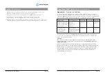
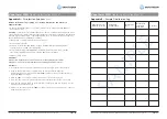
Alarm
Cause
Action
indication
NOTE: To restart after a system failure, the unit must be reset by a momentary pressure on the Power
button. Do not hold the Power button. The alarm will shut off after a delay of about a second, and
the unit can then be restarted normally.
S
S
Water is not filling system properly
Low Water Pressure
Malfunctioning Water or Gas
Pressure Sensor
Make sure VSS-1 spike set is open, and
the tube is not kinked or blocked by
air bubbles.
Make sure gas and water connections are
open, gas can flow to unit, and air has
purged from water system: if not, run
‘CLEANING MODE’.
Send in for service.
Water low
Insufficient gas or water pressure.
Malfunctioning
Water or Gas
Pressure Sensor
Make sure the gas and water circuits are
open and functional and air has purged
from the water circuit if the unit is in
normal operating mode.
Run in “CLEANING MODE”.
Make sure there is correct flow for
cartridge flow rates. If using <5lpm with a
low flow cartridge, a nasal cannula must
be attached.
If a component failure return the unit
for service.
System Failure
Cartridge
Water drops in the circuit will
cause a cartridge alarm; this does
not necessarily mean the cartridge
needs to be replaced.
Section 6
Alarms, Trouble Shooting and Component Change-Outs
6.1
General
1. Periodically check for alarm conditions.
2. Unit will shut down if there is no gas flow. However, flow will not be interrupted if unit
shuts down or malfunctions for any other reason.
3 Unit will shut down if temperature safety limits are exceeded, or if water level is low for
more than 4 mins. However, unheated gas flow will continue.
NOTE:
Should a malfunction occur, indicators on the front panel will light and an alarm will sound.
If the actions listed here do not correct the problem causing the alarm, the unit should be returned to
an approved facility for service.
6.2
Alarms and Troubleshooting
Section 5
Operation of The Vapotherm
™
2000i
5.7
Operations – General Guidelines
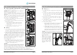
1. Check that water is properly circulating through the machine by making sure the Patient Delivery
Tube is warm across the entire length.
2. If good circulation cannot be confirmed, check that the water flow is not obstructed by air bubbles.
3. Take precautions to minimize cooling of the unheated cannula by trying to maintain contact with
the patient’s skin and insulating the exposed portion of the cannula with bedding.
4. Cartridge door should be closed during operation.
NOTE: Condensation in the cannula may occur at low flow rates. To minimize condensation, these
general guidelines should be followed:
•
If using flow rates less than 5 lpm, do not set the temperature higher than 34ºC.
• The Vapotherm unit should not be in a position where it is cooled (eg. by an air conditioning outlet).
CAUTION:
DO NOT EXCEED flows of 8 lpm for VT01-BS and 40 lpm for VT01-AS cartridge.
DO NOT SET flows below 1 lpm for VT01-BS.
WARNING:
Never occlude the nares with cannula.
NOTES:
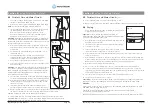
It may become necessary to disconnect the cannula from the Patient Delivery Tube for short periods, such as
when moving a patient out of a radiant warmer. At flow rates less than 5 lpm, cannula disconnection will
activate a system failure alarm, requiring a reset. To avoid this alarm, briefly turn off unit by pressing the power
key once. The display will show two bars. Disconnect the cannula from Patient Delivery Tube and move the
patient, reconnect the cannula, then press the power key once more to restart the unit.
A SYSTEM FAIL (88) alarm will activate if there is insufficient gas pressure in the manifold. If no cannula is fitted,
flow rate at startup should be at least 5 lpm. The minimum flow rate for operation is 1 lpm if a neonate, infant
or premature-sized cannula is fitted, 5 lpm with a pediatric cannula, and 8 lpm with an adult cannula.
Cannulas are single use patient items, dispose of as necessary or according to your institution’s guidelines or
when visibily soiled or excessively wet from secretions. Weekly change out is recommended to avoid any
hardening of nasal prongs.
An air lock can develop at the pump, preventing normal water flow. Try restarting the unit in
cleaning mode.
Operating Instruction Manual
Page 12


