2920 Float & Tape Transmitter
4 Wiring
18
Installation and Operations Manual
Safety Guidelines
• Maintenance should be performed only by authorized personnel.
• Caution should be exercised when entering any area that is posted or otherwise
assumed to contain hazardous gases. Always follow local guidelines.
• Obtain a hot permit before removing the transmitter cover with power applied.
• Before installing/repairing any wiring to the 2920 FTT, make sure that the power is
turned off at the main circuit breaker or switch. The power switch should be locked in
the OFF position and labeled to prevent other personnel from turning the power on
during installation.
• To prevent shock hazards, the housing of all units should be properly grounded in
accordance with the National Electric Code. A grounding conductor should be wired
to the grounding terminal provided on the 2920 FTT.
• Do not apply power to the transmitter until all wiring connections have been made
and the cover of the transmitter has been replaced.
• Do not apply power until the instrumentation’s communications network has been
checked (see “Checking Line Resistance”).
• Do not apply power in a hazardous environment until the explosion proof enclosure
is closed.
• Incorrect field wiring connections can damage the transmitter electronics and cause
system malfunctions.
Checking Line Resistance
The specification, quality, and condition of the cable between the 2920 FTT and the control
room is critical to the reliability of the entire system. Before wiring the 2920 FTT(s) to your
system, ensure that the field wiring meets the following criteria:
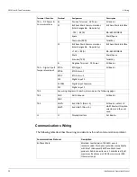
• The number of transmitters wired in each area does not exceed 31 (MODBUS) or 10
(Bi-Phase Mark). See “Communications Wiring” for more information.
• Wiring distance of the entire communications network does not exceed 10,000 feet
(Bi-Phase Mark) or 4,000 feet (MODBUS).
• For Bi-Phase Mark, the wiring loop must not exceed 200 ohms (100 ohms per wire)
and cable capacitance must not exceed 1 microFared (1
μ
F
).
• For Mark/Space, the number of transmitters wired in each area must not exceed 50.
• For Mark/Space, the wiring distance of the entire communications network must not
exceed 10,000 feet.
• For TankWay, 4-Field Wires, use 20 AWG minimum.
When existing or proposed wiring does not meet these limits, the Varec Engineering
department should be consulted for a specific evaluation.
Summary of Contents for 2920
Page 2: ......
Page 16: ...2920 Float Tape Transmitter 1 Introduction 6 Installation and Operations Manual...
Page 114: ...2920 Float Tape Transmitter 6 Bi Phase Mark 104 Installation and Operations Manual...
Page 120: ...2920 Float Tape Transmitter 7 MODBUS 110 Installation and Operations Manual...
Page 126: ...2920 Float Tape Transmitter 9 L J TankWay 116 Installation and Operations Manual...
Page 158: ...2920 Float Tape Transmitter 14 Ordering Information 148 Installation and Operations Manual...
Page 193: ......

